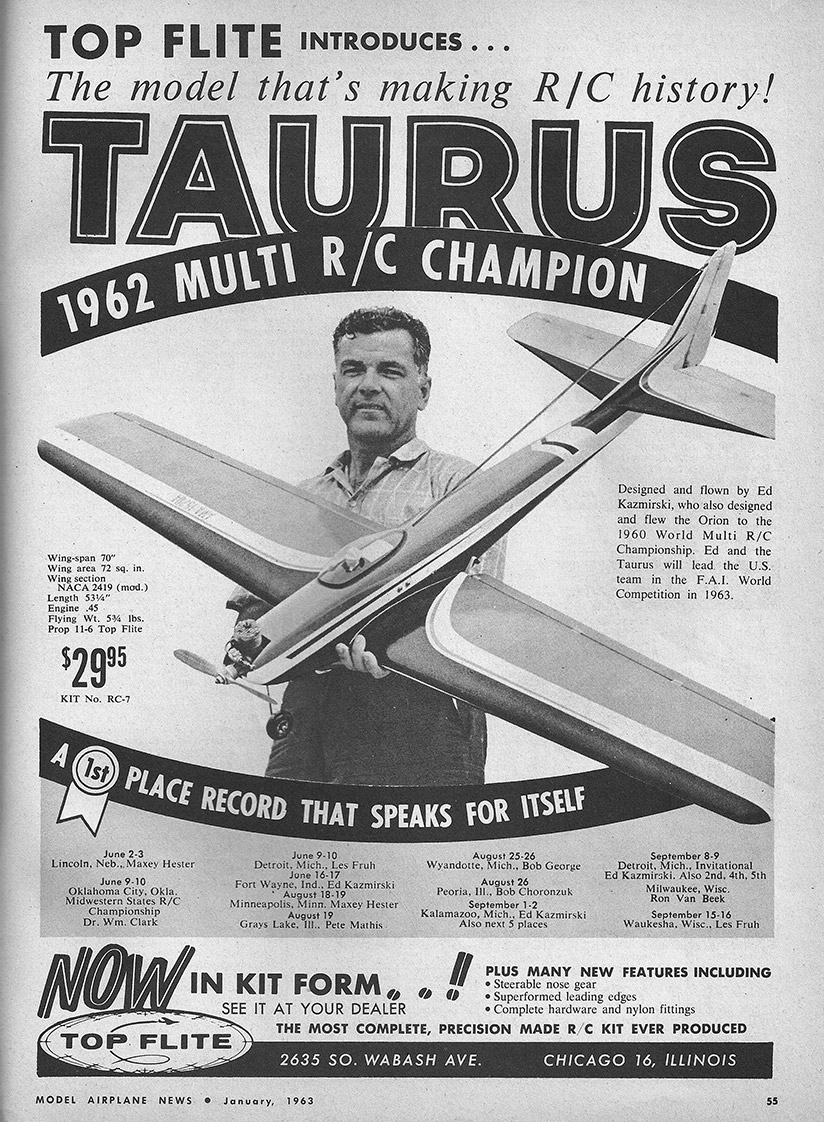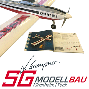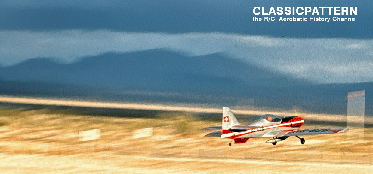

Today I am showing replicas of the first world championship model in RC1 aerobatics history. Designed, built and flown by the US-American legend Ed Kazmirski. Ed became world champion in model aerobatics in 1960 with his ‘Orion’. Our blue model is owned by our long-time friend Karlheinz Schmid, the red plane can be admired in the Leodolter Museum in Hittnau / Switzerland. The blue plane was built by Günter Hoppe, the red one by Guido Patrocini. The story can be found here…
The Orion, like any airplane design, is one answer to a problem. The problem, in this case, was the need for a ship capable of more nearly perfect maneuvers. Through 1959, I had flown the Astro Hog design, but with various modifications to improve maneuvers. But it takes more than an Astro to Beat an Astro.
While it is always possible to cite areas of possible improvement in, any design, it is not possible to off-handedly put a design on paper that would achieve these improvements, especially when the existing design is conceded everywhere to be the airplane for multi competition.

A list of performance standards must first be established. By studying our own past contest experiences, certain weaknesses, which occurred during various maneuvers with our past ships, were evident. Mainly, it was decided that a good contest ship had to be smooth flying at all times.

Keeping all of these things in mind, an entirely new design was worked out. The ship then went through a development period of about five months. During this time we worked on everything we felt would increase the performance of the ship. This resulted in much flight testing, working with “moments”, center of gravity locations, and wing and stabilizer areas. A good design involves a lot of compromises.

For a long time, we felt that the stab, being mounted on the bottom of the fuselage in line with the wing “wash” caused some problems in certain flight attitudes. Even in dead calm evening air, we noticed some buffeting in last year’s ship. This we thought was caused by wing wash over the stab. ‘The new design has the stab mounted well above this area, plus being trimmed to fly tail high in level flight. This high stab location does appear to give an improvement in smoother flight.

Since ailerons are used a good part of the time, any improvement made here would be a big help. We went out to the local airport with a pad and made sketches of the many different types of hinging arrangements found on full-scale aircraft. They all seemed to follow a regular pattern except’ the Piper Apache. Its ailerons were hinged below the bottom surface and behind the leading edge of the aileron. After making a mockup of this type of hinging and studying its action, we found that it might solve some of our problems.

When we apply right aileron, that aileron goes up, and the left aileron goes down. At this time we want one unit of pressure pushing the right wing down, one unit of pressure pushing the left wing up. Also, we should have one unit of drag on the right wing and one unit of drag on the left wing. This would give us a good turn or a good roll. On the conventional aileron this is where we get in trouble. When the left aileron moves down, we develop lift on the left wing panel.


Now let us take the new aileron set-up. As the right aileron moves up, the leading edge of the aileron pushes its nose below the bottom surface of the wing. This does two things. It causes drag on the right wing panel to equalize the drag on the left panel.


While working with stab areas and CG locations we found, that by reducing the stab area and moving the CG back, our landing approaches were improved. The ship was much easier to land because of a lower landing speed. Our thinking on this is that, while full power is on in high speed flight, the stab does a good job of holding the airplane in its proper pitch attitude. As we reduce power during the landing approach, the airplane naturally slows down. Now, at this point, with the stab loaded by the CG being considerably farther back than normal and the stab area being on the small side, the plane tends to sink slightly. This gives us, in effect, a greater angle of attack; and results in a slower landing speed.

The ship originally was flown with a straight wing at about a 17-ounce wing loading. On windy days the approaches were just too slow, and so we decided to reduce the wing area. We made a layout of a tapered wing (maintaining aileron moment) using about 100 square inches less area. Flight tests with tapered wing showed a big improvement in the performance. It is well worth the additional time required for construction. The smooth-ness of flight is so obviously improved that we feel the old straight wing is now obsolete as far as a contest ship is concerned.


Now take a ship that flies at 50 mph and stalls at 20 mph. Flying straight and level, we call three loops. Being well above the stalling and unstable speed the ship goes through the three loops effortlessly. In fact, if we continue to hold back on the stick the ship would loop indefinitely. These figures, of course, are only approximations.

We believe that one reason why low wing airplanes have a reputation of being hard to fly, is because, originally, they weighed in at 7 to 8 pounds. With a “35 engine” they were continuously near their stalling speed. Thus, they were quite unstable and very difficult to fly.
When the ’45 RC” was installed, their flight characteristics improved. So one might say, why not install a “60” and further improve performance? Our answer is that there is a limit to the size of engine we can use simply because we cannot stand the vibration, nor the radical weight increases. We know that if we lighten and clean up our ship our speed goes up with no problem at all. Most people will say a fast airplane is hard to fly and we felt the same way until we looked into the problem.

We observed that fast ships flying in various contests were wild, not very smooth and looked like they were difficult to handle. Analyzing the problem we found that they were being overcontrolled. As the speed of the ship goes up, the controls must slow down and the control area be made smaller. We have done quite a lot of experimental work along this line and find the results very gratifying.

Let us consider the elevator. First we reduce the area. Then, by using a longer elevator horn, we reduce the rate of travel and at the same time reduce the deflection. The proper balance of elevator area and horn length was achieved by trial and error. We want just enough elevator for nice round loops, both inside and outside. Also, we must have enough elevator to make the airplane spin. Here we compromise, but we end up with less elevator than we previously used. This does wonders for smoothness but, just as important, it helps our landings. We can use a smaller elevator with less travel because our ship travels faster. At this speed the elevator is effective because of the speed. But let us cut the power and make a touch and go or a normal landing. As the airplane slows down, the elevator becomes less effective and we find we can use more up without the airplane ballooning. This makes for smoother approaches. It is interesting to note that in a full scale airplane the elevator is full up on the touch down. Perhaps we are approaching this in our models.
We talked about cleaning up the air-plane and felt the fuselage was the place to do it. Early RC were quite bulky. This was necessary because all of the components that went into fuselage compartments were large and bulky. In the last few years all of the components have been get-ting smaller. This allows us to design a fuselage that has a smaller cross-sectional area. The fuselage is cleaner and lighter because we use less material. After some thought we came up with the soft block construction shown on the plans. This al-lows us to develop the contours we want for a clean ship. The surprising thing about this type of construction is that it is fast and simple to build, and also light in weight. All top blocks should be the softest balsa obtainable. The fuselage I used last year weighed 20 ounces. At the same stage of construction, the ORION weighs but 13 ounces.

Streamlining the nose is a big help mainly because it allows the prop to work more efficiently at its inner diameter. We noticed a vast improvement in ground handling with this fuselage as it does not tend to weathervane nearly so much.

Construction
The modeler building this type of ship has had some experience so rather than go into building details, we will touch on important highlights. It is very important on a modern multi ship that all surfaces be true. If we have a wing with built-in warps, it is practically useless for contest work.
A wing panel can be no truer than the surface it is built on. A piece of %-inch plywood at least 12″ x 36″ is fine. How-ever, even this may have a slight warp or twist in it. By shimming and clamping this to your work bench until every portion of it is level you will assure yourself of a fiat working surface. This is very import-ant. Use a good sensitive level.

The system we use for building the tapered wing is to work from the chord line. Have the chord line parallel to the working surface. After cutting out the ribs, the chord- line should be marked on each rib with a ball point pen—this line is shown on the plans. By shimming the trailing edge of each rib until each chord line is parallel with your working surface you will come up with a true wing panel.
We have been using with excellent results for about three years the type of wing construction shown on the plans. Balsa wood has excellent tensile and compressive strength with the grain. By put-ting all of the material near the surface of the wing we get more strength. This is because the members are under compression and tension. For this reason we use ¼”x1/2” spars laying flat at 30 percent of the chord which is the thickest part of the airfoil. You will note from the plans that the spars are doubled inboard to take the center section and landing gear loads. If built true, this type will stay true for its lifetime.

Dihedral is 3 1/8″ under each tip rib. Selection of wood is important. Spars should be medium-hard straight-grain balsa. Leading-edge sheets should be soft, as should the outboard ribs. Inboard ribs are medium balsa. Use silk to cover the wing. We used 2″ pinking tape over the center joint of the wing. This adds a great deal of strength to the center joint. This tape should be available at your local airport.

Fuselage sides should be made from one piece if possible. If you do have to use a splice, be careful to get a good strong joint. After cutting out fuselage sides, the “0” line shown on the plans should be transferred to the fuselage sides. This is important because we use this line for setting up our wing and stab incidence angles. All fuselage blocks should be soft balsa. Top deck blocks are installed after the sides are joined together. With all blocks installed the fuselage looks quite crude, but about an hour of carving and sanding will transform this into a real streamlined beauty. We use Minnesota Mining Production Finishing Paper-80 grit—for roughing and 150 grit for finishing. This paper is available at most hard-ware stores.

The stab is completely finished, including the covering and installation of the elevators, before it is fitted to the fuselage. Do not cover the stab center section though where it attaches to the fuselage, nor where the rudder is attached. The stab is then permanently attached to the fuselage at these uncovered points.

When the stab is ready for fitting to the fuselage, the fuselage should be set up with the “0” line parallel to the bench top. That is, the motor mounts would be at 0°. At this point the stab should have 3/16″ of positive incidence in 6″. The wing should have 1/2″ of positive incidence in 12″. This gives us a decalage of M” or about 1/2° of incidence. The CG is shown on the plans and is 41/2″ behind the leading edge of the wing at the fuselage contact point.

A further note -of interest concerns the fuselage which should be covered with silk. Give the bare wood two coats of clear dope (any good grade of butyrate dope); sand lightly with 3M Production Finishing Paper # 150. Lay dry silk over the wood and then dope through the silk. Apply three coats of dope over the silk with at least two hours drying time be-tween each coat. When dry, sand it with #150 paper until it is smooth, being careful not to go through the silk. Two more coats of clear dope and a good sanding should give you a smooth finish. Clear dope should not be thinned. Two coats of color will usually cover quite well. Now color dope should be thinned just enough to allow it to flow smoothly. We do no sanding on the color dope. After this has dried several days, one final coat of clear dope from the Aero Gloss spray can will give you a real slick finish that is easy to wipe clean.

Since we can get many points on the ground we find the landing gear quite important. A soft air wheel, preferably a #5 pessary, is best, because, if the tire is slightly fiat, it naturally takes more power to roll the airplane. Therefore, it is not necessary to idle down too low. Also, the low-Pressure tire absorbs the landing shock much better and eliminates some of the bounce. It is important, too, to toe out, the wheels to about 11/2°. The reason for this is, if on touchdown, one wheel touches first, the toe-out will pull out and touch the other wheel down. This works the same way on a crosswind take off.
It was also discovered by experimenting that if the idle bar in the glow plug is at 90° to the axis of the crankshaft a better idle is obtained. The reason is that the idle bar is parallel to the flow of gas through the cylinder. This reduces the tendency of the fuel to quench the idle bar. It is necessary to use washers of different thicknesses to bring the bar to this position.

This is a good fuel blend: 4 parts Methanol-1 part Bakers AA Castor Oil; add 32 drops of Amyl-Acetate per quart of this blend. This gives us a fuel that keeps our K & B 45 running cool and yet delivering full power. Idling is excellent with this fuel.
We do not claim that all of the ideas presented here are original, but merely present them as general information. In looking over the design you will find that we have utilized the good features found in existing designs. To this we have added a number of, our own innovations that we feel give us new possibilities in the “multi” flying field.
Ed Kazmirski 1961
Images: Burkhard Erdlenbruch, Willi Streil, Urs Leodolter