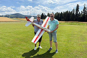
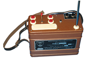
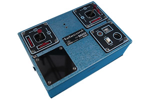
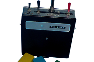
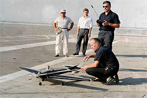
Retroday 2025 – Urs Leodolter presents one of his exhibits: PELIKAN, a construction by Bruno and Emil Giezendanner from 1966, lovingly built for Urs Museum by the Swiss Willi Böni.
Here is the original report by the Giezendanner brothers from 1966:
Despite the relatively high level of radio-controlled acrobatic flying, there are still numerous multi-channel pilots who, when building their models, always have chance on their side, so to speak, to solve important design problems. Depending on their mood, they change, improve or even “modify” their models. One time you bring your model with a forward sweep, another time with a backward sweep, once with, once without or a negative dihedral.

However, anyone who dares to ask the designer in question about the reason for the sudden switch from parallel surfaces to trapezoids will either hear a highly unorthodox, personally coloured “theory of flow” or be stared at with pity, as if he had just asked why the bananas were crooked. However, to prevent all those modellers who pursue their hobby in the manner described from declaring war on me (which, by the way, would do them no good, as I am not under arms and am an outspoken pacifist), I am prepared to take up the cudgels for them.
However, if you want to achieve better results in the “high school” of model flying and even have a part-time job, you will hardly find time to indulge in your ingenuity more than occasionally in order to constantly create new prototypes.
He is much more likely to stick with his tried and tested model – whether this is his own design or a commercially available one – and gradually familiarise himself with the characteristics of his machine through tireless training, which, in addition to routine and safety, will also help him to achieve a balanced level of performance.
Of course, even the acrobatic pilot will not be able to avoid adapting his model, usually with minor modifications, to the latest state of control technology, the requirements of the FAI programme and other regulations.
What you want to know
The PELIKAN 64 was specially designed for competition flying in the RCMM class (multi-axis controlled acrobatic flight) and forms the conclusion of a development series of four low-wing models, without secondary branches, some of which have been discontinued and some of which are still in development. The technical details to be mentioned are the swept leading edge, the low-loss aerodynamic wing angle (which was already successfully used by Gustav Sämann) and, last but not least, the extraordinarily light construction.
These are the main features of the PELIKAN, which have prevailed from the beginning to the latest model and undoubtedly contribute to the fact that it also seems to be proving its worth in the new era of RC acrobatic flying in Europe – proportional control and the new FAI programme. But more about that later.
Technical data:
Wingspan: 1.620 m
Fuselage length: 1.36 m
Total surface area: 49.32 sq cm
Weight: 2500 to 3200 g
Motors: 8 to 10 sq cm
Remote control: 8 to 12 channels
The wing
The construction of the PELIKAN is kept simple and light. For the wing, we have dispensed with the much-vaunted “foaming”, including veneer and contact glues, as we have to watch time and again how stable polystyrene surfaces are crushed beyond recognition in crashes from great heights, just like our balsa wings. Cleanly built balsa surfaces are amazingly stable, torsion-resistant and light. In addition, the PELIKAN was built for flying and not for crashes. Anyone who absolutely needs so-called break-proof wings for their flying would do well to refrain from taking part in acro championships for the time being.

The support added to each rib, which is caused by the setback, can also be easily replaced by two conical battens, which are placed on the slipway under the rib ends. The six ribs that have to support the grooved undercarriage beams and the spar joint must be reinforced with light 2 mm or 3 mm plywood. Rounding the leading edge moulding with a “David plane” requires a little dexterity; if you want to be on the safe side, plane less and sand the leading edge radius afterwards. We have dispensed with edge bends of any kind in favour of straight end ribs.

The fuselage
The fuselage was kept in a simple box construction like the “Orion”, “Taurus” etc. Triangular straps and a 10 mm deck board round off the top of the fuselage. These triangular mouldings are glued to the pre-cut and reinforced fuselage sides.
There are two tried and tested ways of assembling the fuselage:
a) On a straight board, lying on your back, with the outline of the fuselage marked out first. The correct height of the formers is ensured with appropriate supports. The frames should always be fixed with small nails to ensure a symmetrical hull structure. The side walls are then pressed to the frames with clamps.
We leave the end of the fuselage parallel for the time being; it will only take on its final shape when the rear floor is glued in.
b) If you want to build the fuselage in the normal position, you have to cut out an exact slipway from a beam (fir) on the band saw. After drawing the outline of the fuselage, staple the rear floor and the plywood-reinforced, cross-grained front floor to the slipway with fine nails. Now all three frames can be glued in the appropriate places. Attaching the side walls no longer presents any particular problems.
The covering of the fuselage and subsequent rounding are done last. The flange for the nose landing gear, on the other hand, is screwed to the engine bulkhead before assembly. The elevator and rudder are assembled in the familiar manner and will not bring anything new to anyone who has already built American models. Of course, these stabilising surfaces can also be made in a different way. It seems much more important to me that the elevator runs parallel to the wing surface and that the rudder is perpendicular to the elevator.
Wing attachment
When fitting the wing to the fuselage, it is essential to ensure that the EWD is not altered. The wings are attached using the “Camlocs” that have long been known in America. This type of wing attachment was first described here by Bernhard Huber (“modell” No. 9/64) and has been used successfully. The fuselage and wing are rigidly connected, which also requires relatively clean landings. Of course, the wing can also be attached in other ways; I am thinking of nylon and similar vibration-proof screws or the tried and tested, fuel-slippery rubber bands.
Final work
So much has already been written about covering model aircraft that it would be repetitive if I were to describe this technique in more detail. We cover our models (wing and fuselage) with Japanese paper and use the American Fuller varnish and Fuller colours. Bright colours such as yellow, orange and red are very appealing to pilots and judges. (By the way, acro pilots keep their livery simple and functional, as they are not parrot breeders). We do not cover rudders. We sand them finely, cellophane them and paint them.
Only now do we attach the rudders with plastic hinges or sew them on. Finally, we coat the model with a fuel-resistant, crystal-clear synthetic resin varnish.
For the nose landing gear we use the commercially available struts made of 4 mm steel wire, preferably without shock absorbers and other bits and pieces. If you can use a hard surface runway, you will appreciate a steerable nose wheel and possibly brakes; for meadows and potato fields, however, this makes no sense. The main undercarriage is bent from 3 mm piano wire in a vice and held in place in the grooves of the undercarriage beam with aluminium clamps. Under no circumstances should we use 4 mm steel wire for the undercarriage legs on the wing, as this would put too much strain on the undercarriage beams when landing on grass.

The throttle linkage is guided in a metal or, even better, plastic tube. With proportional controls, care must be taken to ensure that the motor and linkage are connected via a plastic connector, e.g. “Ny-Link”, in order to avoid vibration interference, which tends to occur when metal can rub against metal.
Mixture adjustment is a noble thing and proves itself well; however, if you cannot adjust your engine properly on the ground, it will be difficult to compensate for this “lack of talent” by remote control.
The remote control is installed in the fuselage so that the centre of gravity is in the right place (of course with the engine and silencer mounted), which seems more sensible to me than screwing the receiver battery and lead solder to the rudder.
Flying in
If we have set up the PELIKAN exactly according to plan, the centre of gravity and EWD are correct and the wing is not twisted, flying in no longer presents any problems. A runway will of course be ideal for the first launch. With the PELIKAN flown in, we can of course take off from any mown natural meadow. With a 10 cc engine, the PELIKAN requires an astonishingly short take-off distance. On the runway, 20 to 25 metres is normally sufficient.
On uneven grass, we have to reckon with a take-off distance of 30 to 40 metres, whereby we start to pull slightly after approx. 20 metres in order to relieve the nose wheel and thus reduce friction.
Landing is made very easy with the PELIKAN. With the engine throttled back, fly towards yourself in a wide approach loop. If the model flies too close to you, you can easily bump into it or vice versa.
With a little practice, the PELIKAN can be touched down so slowly in calm conditions that even “old hands” are always amazed. The hovering speed is then not much higher than the marching speed of a man. These minimal take-off and landing speeds allow us to fly really anywhere with the PELIKAN, characteristics that were of great benefit to us when we did not yet have a runway. Back then, especially in summer, we were dependent on every mown field and couldn’t be particularly picky. But anyone who has ever tried to touch down on a bumpy natural meadow at 100 km/h will be able to tell you a thing or two about it. What we therefore needed was a model that would not stall even in an exaggerated flight attitude, i.e. one that would remain relatively stable even when the wing was slowly inflated. These characteristics were undoubtedly achieved by sweeping the wing and the aerodynamic inclination. The low flying weight also contributes to the low critical speed.

Of course, the task of an acrobatic model places limits on stability. For example, a model with too much sweep proves to be overstable and sometimes presents insurmountable obstacles to flying certain manoeuvres.
Despite its low flying weight, the PELIKAN remains steady and stable in the air even in strong winds. In inverted flight it is extremely good-natured and does a great disservice to the theory that models with symmetrical wing profiles are easier to fly on the back than those with semi-symmetrical ones. (Incidentally, this has long been proven by Ed Kazmirsky.) The speculation of equal flight characteristics in the inverted and normal position remains, as I said, only theory and proves once again that an aeroplane must never be judged by such details alone, but that the overall concept must be considered as the interaction of many details. The inverted flight characteristics therefore do not depend on the profile alone; the EWD, dihedral, sweep, fuselage cross-section and position of the centre of gravity (high or low wing) also play a decisive role.
The low flying weight proved to be very advantageous, especially in recent years, as in 1965 the silencer was declared mandatory for regional and national championships in Switzerland for the first time. Even for the “flown roll” (5 sec. duration), as prescribed by the new FAI programme, lighter models proved to be very effective.
The PELIKAN is ideally suited for the installation of proportional control and opens up a huge range of new possibilities for experienced acro pilots; however, it will make many things easier for beginners to aerobatics, as this type of control is better suited to their flying skills.
Text: Gebr.Giezendanner
Photos: Johanna Huang, Burkhard Erdlenbruch