

Today I received the sad news, one of my best long-time friends, -Jörg Tetzlaff-, passed away after a short, serious illness at the age of 63 years. He was one of the best model builders I ever knew. As teenagers we had learned to fly together. He was a gifted model builder, all his planes were works of art. At the age of 15, Jörg was already building exhibition models for Aeronaut, among others. Now in retirement age we had a lot of plans, unfortunately it was not meant to be. My deepest sympathy and condolences go to his family. Dieter
Review 1987: As the interest in models suitable for the F3A-X program is growing, I would like to report on my CAP 21. This model is produced and directly distributed by Toni Clark.
This plane is an exact replica at a scale of 1:3.4 of the CAP 21 No. 001, the prototype which was represented at the World Aerobatic Championship in the USA in August 1980.
A plain box contains everything you need to build the CAP. Because I had already had the construction plan sent to me beforehand, I did not need to go through the individual parts unprepared. The comprehensive plan is on a scale of 1:1 with an extra fuselage plan and the excellent detailed sections are to the same standard as the construction kit parts. All the shaped parts are sanded and fit exactly.

The individual parts can be easily found as they are packed into individual assemblies with the help of the 7-page parts list. If you have not read a book for a long time, you can also ask for the 17-page construction manual. If you build according to the instructions, you really cannot do anything wrong, and forgetting important components is also impossible. I have simply crossed out every section.
Building
The fuselage can be built on a flat building board with the separate fuselage building plan. The front fuselage side panels are already cleanly prepared. Also, the fuselage corner strips are profile milled and of very good quality. This applies to all parts. Once the fuselage box is assembled, the construction continues with the center wing section. It can be assembled without any problems by using the Abachi wooden strips. The windows next to the pilot seat of the original are used as cooling air outlets on the model. In order not to have to handle a large wing area, the center section is now dowelled.

The first step in wing construction is the gluing of the 2 mm balsa panels. The main spars of 8 x 5 balsa and 8 x 3 pine are also glued. A special feature is the fixing of the landing gear. The fixing panel for the undercarriage, made of 6.5 mm birch plywood, is glued into grooved auxiliary ribs which are also 6.5 plywood and have already been predrilled to save weight. The undercarriage legs, made of 5 mm duralumin, are fastened with 3 M3 screws. This enables quick assembly during transport. After the wing has been framed, you need to decide how to link the four ailerons.

There is a choice of using either 4 servos in the wing or 2 servos in the center section and linkage via rods with angle levers. The latter option offered me the following advantages.
It was marked on the plan and the lower weight in the outer surface results in better rolling characteristics. Regarding the division of the controls, it should be said that the intention is not to increase the construction effort, but, as with the original, to avoid the risk of aileron flutter. Thanks to a detailed description, the planking of the wing with contact adhesive is not difficult at all. The finished wing halves are simply placed on the center piece, aligned and glued. If you jig the wing in a Styrofoam stand in “crash position”, you can glue the milled obeche fillets.

The ailerons are also rounded off at the leading edge and are fixed with stable hinges. The hinges consist of two Nylon 5mm bolts, 25 mm long and are pinned with a steel axle. The assembly is done by simple drilling, whereby a stepped hole of 5 and 9 mm is drilled in the ailerons. This is necessary because the aileron is shrouded and the axis of rotation of the hinges is located within the aileron.

The elevator is built in one piece on a jig. A striking feature is the very stable connection of the halves of the elevator which are linked with a 12 x 12 mm pine strip, which at the same time enables the large elevator horn to be attached. After gluing in the reinforcing blocks for the rudder hinges (double hinges on the outside) and reinforcements for the tail unit attachment, the planking is then completed. If both sides are planked, the rudder can be separated from the damping surface. The tailplane is fixed with 3 M3 Allen screws. This method of attachment makes it possible to remove the tailplane with its built-in servo for transport. The installation of the servo in the tail unit allows the use of a short linkage rod of 3 mm steel rod in combination with a strong clevis. You get a backlash-free and extremely stable linkage.

Tailplane and rudder are assembled in two halves, planked and then glued. Fully shrouded elevators and ailerons. Abechi triangular strips and deep-drawn foam lugs are used for this purpose. The styrene noses are glued and sanded with super glue. As the rudder should also be removable for transport, the axles are removed from the hinges and replaced by an inserted steel wire.

The rear landing gear is mounted on a recessed plywood plate, which also accommodates the lower rudder hinge. The linkage of the undercarriage and rudder is done by means of cables. They are attached to an intermediate lever in the front part of the fuselage, with damping springs attached to the undercarriage linkage.
The lever is linked by a short push rod. The final work on the tail unit is the attachment of a light GRP fairing and the gluing of the wingtips.


The rudder is aerodynamically balanced it also requires approximately 30g of lead as a mass balancer. Thus, the servo only needs to apply the pure rudder pressure. The remote servo is installed in a box made of 5 mm balsa wood. This box protects the system from the heat of the tuned pipe inside the fuselage. The aileron servos are also protected against heat by a cover. The fuel tank is placed on the system box. The fuel tank receives its cooling air through a cardboard tube directed at the tank. Once all the fittings have been installed, the fuselage is planked. The planking has 3 parts at the front and 2 at the rear. Since it consists of 3 mm balsa, it is necessary to bend it forward. Allow the parts to dry overnight then continue with the assembly of upper decking.

The bottom of the fuselage is planked with 3.5 balsa running across. The very light, white coloured engine cowl is available in two parts. It can be screwed (like the original) or glued. I glued it and after painting I screwed the screws in. It is fixed to the fuselage with 15 screws. Because they would not hold in the balsa wood, small plywood plates are embedded.
With the build completed, cover the airframe with tissue applied with paste.

Once you have screwed on the very clean smoked glass canopy, you get to the most beautiful part. Decorating with the excellent decorative sheets is a lot of fun. The whole finish added 580 g to my CAP, resulting in a total weight of 7600 g compared to 7400 g stated by the manufacturer. To my delight the center of gravity was correct without adding weight.

The construction time for my model was 3 months.
Since I have gained enough experience in applying quirks when performing out the out-of-cellar carrying, here is another tip: after treatment with a film sealer, surfboard packaging envelopes are excellently suited as flat bags.
On the day of the maiden flight the sun was shining beautifully, but it was quite windy. The built-in Quadra showed itself from its best side after a tank filling. Without changing any settings, it ran cleanly through and could be throttled very low.

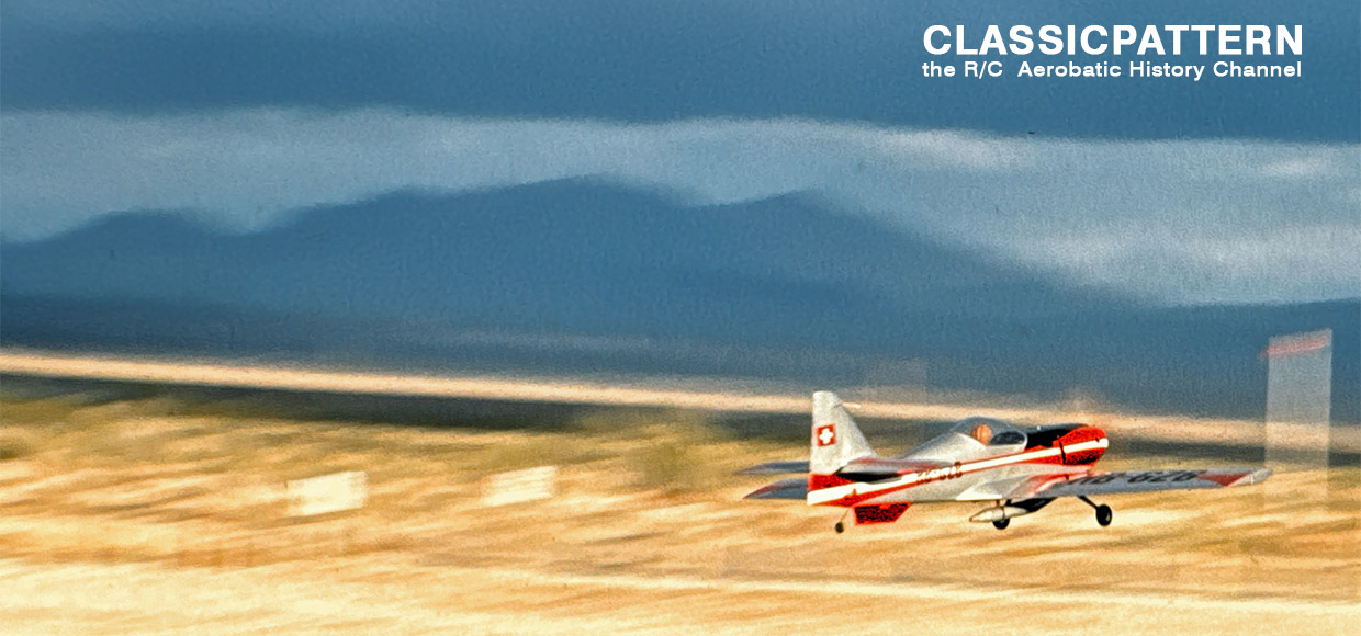
Two short roll tests showed a strong reaction to rudder deflection and the expected roll-out distance. The start was on our hard runway. Due to the somewhat fresh wind, the CAP was already in the air after a short roll distance and had to be pressed a little. The immediate and exact reaction of the model to every rudder movement was striking, which encouraged me to see what was behind it after a trimming circuit. Despite the huge aileron deflections, all roll figures can be flown wonderfully smoothly and accurately. Thanks to the large fuselage, the knife flight requires little rudder deflection. Cracked rolls can be flown on the side. However, the CAP is not suitable for speed flyers. There is hardly any increase in speed in a nosedive, and the model behaves in the same way in pushed and pulled figures. This results in a balanced and extremely elegant flight pattern.

I must say that I have never tried so many figures with any model in the first 10 minutes as with this CAP. Obligatory was now overdrawn in safety height. Here it can be seen that the CAP only goes over the nose as long as you keep your fingers off the rudder. Not unmentioned I would like to leave the turns. They are not tilted or pushed around – but flown. The landing is no problem at all. The flat glide angle allows a clean approach. Touching down and taxiing back to the take-off box is the end of an inspiring first flight.
In summary, it can be said that the design of the model should be optimal from a structural and aeronautical point of view. It is to be hoped that even more pilots will not shy away from the effort and build the large model for the RC 1X program.
Specifications:
Scale: 1:3,4
Wingspan: 2,38 Meter / 94 inch
Length: 1,90 Meter / 75 inch
Powerplant: 50 – 62 cm3
Wing area: 83 dm2
Flying weight: 7,5 – 8,5 kg / 16,5 – 19 lbs
Area loading: 90-102 g/dm2
www.toni-clark.com
Author: Jörg Tetzlaff 1987
English text: Thanks to Martyn Kinder for support
Images white Cap: Jörg Tetzlaff
Images blue Cap: Karl Paul
Images other white Cap: Philippe Souperon