A Bird Named Banshee by Jim Martin
The Banshee is a very capable R/C Pattern-Stunt aircraft, intended for competent radio flyers. Listen all you seekers of a new contest design, I have something that will put you in the Winner`s circle. Look at what I’ve done, I’ve changed the whole concept of competition aircraft.

Of course the first qualification you must have to do all this is a degree in aeronautical engineering from Snoopy’s Institute of Dog House Design. After completing a six year course, I set out to create a Pattern ship that would stun the world. Compiling all my notes and referring back to my
textbooks, I started laying out a set of plans, remembering my new creation was to be a totally different approach. So here is the step-by-step resume of the six month’s of labor that I put into my plans.
The very first step was to choose a power source that no other competition flyer was using. I spent two weeks looking and finally I was rewarded for my efforts when I walked into my local hobby shop and spied a 10cc (.61 cubic inch) two-cycle R/C glow engine which the legend an the box revealed to be a Webra .61. I now had a power source (to put it mildly) and no means to attach it to the airplane. So, back to the old drawing board to design a motor mount. After praising myself as a genius for designing the perfect mount, 1 was informed of a mount commercially available, exactly the one 1 had labored over with my crayon. I went back to the shop and purchased the item, saving time if not money.

Now, with the engine installed in the mount, I still needed something to mount the mount on, and here is where my six years of inhaling Snoopy’s wisdom came in handy. After four hours of pouring over my notes, I decided to use a piece of 1/4″ live ply plywood. I needed a place to hide the tank and made an enclosue for it. Holding a dog’s degree in aeronautical engineering, I knew I couldn’t get enough Lift out of what I had, so I decided to use a wing. Great, but it wouldn’t balance. To get a C.G. that would fall somewhere between the leading edge and the trailing edge, I had to extend the fuselage back. I finally wound up with a fuselage that was some eight feet long. I knew I couldn’t get it in my car, so I had to shorten it. I added weight to the fuselage in the form of a stab and rudder. Now see how different my approach is? I was the proudest person in the world when I finished my new bird. I was so sure that nobody had ever designed an airplane in this manner and I knew I would never see another like it (Curses an you model designers!)
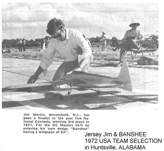
In no way is the Banshee a trainer! It wasn’t meant to be. It is a very fast and groovy Pattern aircraft, designed to perform the whole AMA or FAI Pattern and to do it well. The. Banshee is a very clean airplane and you will find its landing characteristics different from most of the air-craft around today, It has great Penetration, so as you throttle back, the speed does not drop off. You are still in command which means you have to slow it down when you turn on final. You will have to start to bring up the nose until you have a nice sink rate set up, but don`t worry, even with the very thin wing, it is not prone to tip stall. This airplane is very much at home in wind, whether it be a crosswind or right on down the runway.
The Construction
With a set of full size plans and the necessary raw materials at hand, start into the fuselage assembly. The 1/8″ x 6″ x 48″ sheet stock pieces serve not only for the fuselage sides, but as the jig itself. Make certain that you use good even-grained wood. Midwest balsa was used on the original. Sight along the bottom edges of the sheeting and true-up as necessary. Two 1/16″ ply doublers are now cut, as per the plans, and laminated into position. I used Southern Sorghum Contact Cement for this, sold by Southern R/C Products. Next, cut the bulkheads and make sure you put reference lines on them for the center-lines. Mark these centerlines, the wing saddle and bulkhead locations on the fuselage sides.
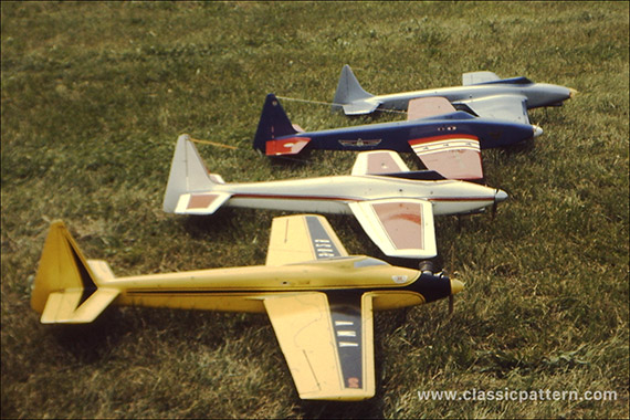
At this point, pick your truest work area and clean off all debris. Mark off a reference line on the work surface to build over. Start things by mixing up a batch of 5 minute Devcon epoxy and with a square handy, glue F2 and F3 in place. Let this set at least half an hour. Next, mark the top and bottom triangular locations, but do not trim the top or bottom of the sides as yet. Using Ambroid Se-Cur-It, glue the triangular stock in place and let it set overnight. Stir up some Formula 42 Hobbypoxy and in-stall Fl and the 1″ triangular gussets. Clamp these firmly and let the work set.

Draw the tailpost ends together and glue, but before it sets, install F4 and F5. Use a small piece of trailing edge stock to strengthen the tailpost. After this has dried, trim off the excess fuselage siding down to meet the triangular stock, using a block plane and sanding block. The top 3/8″ sheet cap is now cemented in place and Ambroid Se-Cur-It is recommended here. By starting at the front and holding it down with masking tape, work along to the F5 position. Masking tape seems to be the best way to hold it in place.

Cut out along the wing saddle, using a hand-held jigsaw. Decide at this point as to where you want to place your servos and make the necessary rails. Relieve the bulk-heads for the pushrods with a small keyhole saw or other tool and trim off the fuselage siding to the 3/4″ triangular stock. Now install the 1/4″ planking lengthwise on the bottom from F 3D to the tailpost. With the aid of a block plane and lots of sandpaper, shape the top of the fuselage to a graceful contour. Install the stab at this time, using Hobbypoxy 42. Make the rudder fin and install, sighting carefully to make sure everything is true.
Attach the engine mount, install the engine and the nose gear. I used Pro Line Retracts on the original, which worked beautifully. The bottom planking under the nose is now added, using blocks close in to the engine. After the glue has set, remove the nose gear and go back to the sandpaper as you shape the front end. The amount of time spent sanding will show up in the finished product. The wing fillets are made at this time out of soft 1/2″ stock and glued into place.

The Wing Assembly
As the first step, make a set of root and tip airfoil templates. I have cut only two sets of foam wings, so I do not feel qualified to recommend any exact procedure for foam cutting. If you are not knowledgeable in this area, have someone cut your wing for you. Covering the foam cores is very simple. Choose very soft and light 1/16″ balsa, then true up all edges and Butt-join the sheets, using Ambroid Se-Cur-It. After the wing skins have dried, sand the entire skin using 320 grit wet or dry, used dry. Now sand the foam cores and vacuum all the dust off both cores and skins. Using a good contact cement such as Southern Sorghum, brush on a very thin coat on both the foam core and the 1/16″ balsa skin. Let this set at least 25 minutes, then you are ready to cover the foam.
Pick a good, true work surface and lay the balsa skin down, making certain that you note where the trailing edge is to be started and that the balsa is laid down nice and evenly. Starting from the trailing edge, take your time and work toward the leading edge.
Mix a cup of warm water with two tea-spoons of ammonia M it and with a sponge, wet a 2″ strip where the leading edge will wrap around. Be careful not to get water on any glue joints. Let the water soak in for a few minutes, then continue completely around the leading edge to the trailing edge. Set the panel aside and do the other core in like manner.
The next step is to measure and mark out the ailerons. Be sure you allow for the facing of the aileron and the facing on the wing. Refer to the plans for three measurements. Mark the centerline of the torque rod on the bottom of the wing, then channel out an area large enough for you to set the torque rods in. The torque rod should be made of 5/32″ dia. piano wire, running through aluminum 5/32″ I.D. tubing. Hold in the wing using Hobbypoxy #2, and replace the wood you removed. Set the wing aside to dry.
The facing is now added to the wing and aileron. Pullowing this, you should prepare the aileron linkages. A 99 degree band must be made and inserted into the aileron. Bend the 5/32” dia. wire and file a flat spot prior to installation in the wing. Use a Fox wheel coller and drill another hole at 99 degrees. Silver solder a long 4-40 bolt into the new hole. Using a nylon aileron horn, tap for 4-40 and thread it cute the bolt you have soldered into the wheel endfar. The set screw will lock ente the flat spot you have filed on the torques rod, holding it in place. As added protection, use Loctite on the screw set.
Finishing Techniques
Here are a couple of proven techniques which you might !lite to lese for a really great finish on your airplane.
Technique #1: Finish-sand the raw balsa with fine sandpaper. Rub the balsa with foam rubber to eliminate fine balsa fibres that will “come up” during the application of the first coat of Hobbypoxy clear.
Apply four coats of Hobbypoxy clear, allowing four to five hours drying time between coats. Sand and then flow on one coat of Hobbypoxy filler. Wet sand and clean thoroughly. This can be done by washing off the surface with a rag moistened with Hobbypoxy thinner. Spray or brush on three coats of Hobbypoxy color and trim to suit.
Technique #2: On my first Banshee, I put three coats of clear dope on, then sanded the entire fuselage and covered it with 00 grade Silkspan. I then added three more coats of clear, sanded and then filled in any imperfections with Hobbypoxy “Stuff’. I brushed on three coats of thinned Hobbypoxy filler and sanded between each application. I used Slick-Tac by Citizen-Ship to cover the wing. Two coats of auto primer were sprayed on. This was then wet sanded with 400 grit paper, after which I sprayed on the final color.
Here’s where I open up a can of worms. When I drew the original plans for the Banshee, it was to be a mid-wing. After flying a mid-wing for over a year, I saw many advantages and disadvantages. I settled on a wing location below the thrustline and the stab above the thrustline. The main reason was for pitch control. The true mid-wing has a tendency to “hunt” a neutral, which makes one more thing to worry about when flying in competition. The airfoil is a modification of the airfoil that Hal deBolt has used for years and it has worked just fine for me. I used a diamond airfoil on the stab and I believe it was well worth the extra effort in construction. I go along with Jim Kirkland that the air foiled stab versus the flat foil is the smoother of the two. From what I have seen so far in the Spring of ’71, it looks as if all the top flyers are using an airfoiled stab.

In my estimation, the fuselage side area, fin and rudder are very critical. Most people who saw the design before it flew, said that they thought I had about half the amount of fin and rudder that it should have had. Well, I’m happy to say they were wrong. The fin and the rudder worked out to do exactly what I had hoped they would. There is very little tendency to weather vane in a crosswind and yet it is more than adequate for knife-edged flight. The rudder can be used in loops for correction, without the normal tail wiggle and the best is that the rudder will not cause a roll.
If you should decide to build a Banshee, I wish you many happy flights. It´s a spirited kind of animal and should serve you well in competition.
Specifications:
Wingspan: 1,58 Meter / 62 inch
Length: 1,30 Meter / 51 inch
Engine: 10ccm /61
© Jim Martin USA
