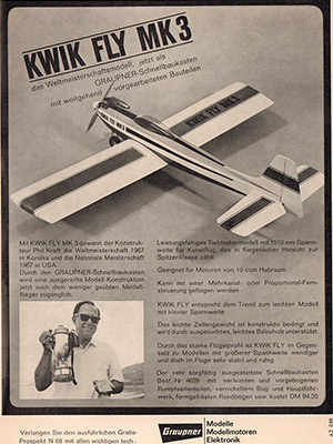
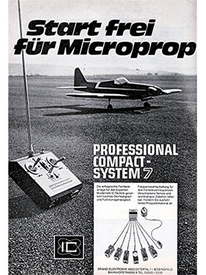
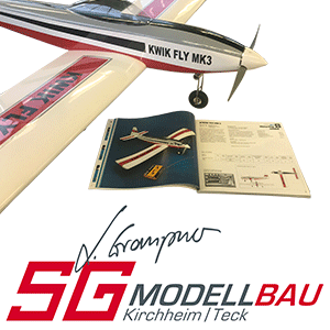
Wolfgang Schwarze was a former employee of the Graupner company. He worked in the development department. In his spare time he flew in RC1 competitions, not at the very front, but he was far from bad.
In the seventies, Wolfgang was an RC motorized flight instructor in the Baden-Württemberg Aviation Association. He retired from this honorary position in 1980. I took over the job. Wolfgang and I were friends and he gave me the best introduction to this job as a sports official.
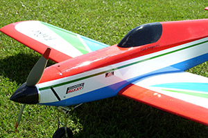
Wolfgang developed his own aerobatic model in the seventies, the
Here is the construction description:
Several BW state championships were won with this aerobatic model and variants of it in the 1970s. The design goal was to create a model that was as light as possible with neutral flight characteristics. The weight of the prototypes was between 2300 and 2900 g, the lighter, the less engine power is required and the less critical the flight characteristics are. The replica is only intended for experienced model builders and RC pilots. And only a model built straight and without distortion will provide the desired good flight characteristics.
Please note: The heavier the model and the higher the motor power selected, the more carefully and sturdily it must be built.
Choice of wood
With balsa wood, care should be taken to use the lightest possible but nevertheless stable long-fiber wood.
Adhesives
It should be mentioned here that many of the prototypes were glued with contact glue. Even the tailplane and wing panels were glued to the ribs. This saves weight, but must be done very carefully! White glue or epoxy resin are more stable, but also heavier.
Motorization
The original models were each fitted with 10 cm3 engines. For reasons of strength, it should be borne in mind that today’s engines have a higher specific output, so that even good engines from approx. 7.5 cm3 are perfectly adequate. With today’s 10 cm3 high-performance engines, a lightly built “Falcon” would probably be overpowered! In keeping with the times, it can also be one of those inexpensive ten-cubic engines with a good muffler.
The engine is mounted using an aluminum back plate or a ready-made engine mount. Installation can be upright, horizontal or inclined at 45 degrees, depending on the intended silencer or the space required for it.
In later model variants, the tank was moved approximately back to the center of gravity so that no load changes occur during flight. However, a fuel feed pump is a prerequisite for this.
Landing Gear
Even back then, retractable undercarriage was predominantly used, as fixed undercarriage accounts for a considerable proportion of the total drag. The decision as to which undercarriage should be used must be made before construction begins so that the components affected by this measure can be modified accordingly. This applies to both the head frame 8 and the wing ribs 55 to 59.
Assembly
This is preferably done according to the numbering of the individual parts and starts with the fuselage.
Parts 1 to 7 are used to make one right and one left side of the fuselage. Glue the formers 8 (depending on the engine and undercarriage) and 9 to the tank support 10 according to the plan. Mark the center of the fuselage (longitudinal axis) on the building board, as well as the center on formers 8, 9 and 11. Glue the fuselage sides to the glued parts 8 to 10. This creates a stable unit. The height of frame 9 is such that the fuselage can be built upside down (rear part of the strips 3 resting on a flat building board). Glue half formers 11 and 12 and the fuselage sides together at the rear end. Turn the fuselage over and glue in the fuselage back formers 13 to 16 and the lower ribs 17. Then adjust and glue the side planking 18. Sand the top edge of these even with the back bulkheads and attach the fuselage backs 19 and 20. Then fit and glue the parts 21 to 23.
When attaching the fuselage floor 24, make sure again that the fuselage remains straight! It is advisable to sand the cabin moldings 25 to 27 roughly before fitting them. Fit and attach the fuel filler cap 28 and its retaining pieces 29. The fuselage head is made from balsa blocks depending on the engine, engine mount, spinner and installation position of the engine. Reinforce the connection between the head bulkhead and the fuselage sides with fiberglass and resin. Now sand the entire fuselage clean.
Horizontal stabilizer
The horizontal stabilizer is built using the sparless shell construction method on the slipway parts shown in the plan. Staple the slipway parts to the building board with pins according to the plan view. Staple the lower planking 30 to this and glue on the ribs 31 to 35, followed by the upper planking 36. Sand the leading and trailing edges flat to accommodate the leading and trailing edges 37 and 38. After attaching the edge bows 39, profile the entire tailplane and sand the edge bows round. Also profile the elevator 40.
Tailplane
Assemble it from parts 41 to 43 according to plan and sand the leading edge. Glue the rudder together from parts 44 a and 44 b and profile it according to the plan.
Align and glue the horizontal stabilizer and fin at right angles to each other and to the fuselage. Sand the fuselage support if necessary. It is recommended to glue a triangular strip (6 mm x 6 mm) with several cuts on the outside of the fuselage between the side of the fuselage and the tailplane for reinforcement. However, this strip is not shown on the plan.
Trim and fit the moldings 45. Glue the tail 46 in place, possibly recessing it slightly into the bottom of the fuselage. Glue the wing attachment carefully into the fuselage using parts 47 and 48.
Wing
It is recommended that the wing is built up in one piece on two chopping boards positioned at an angle to each other. The main spar is underlaid with 3 mm, the rear height is determined by the trailing edge. The protruding part is cut off later (see profile cuts).
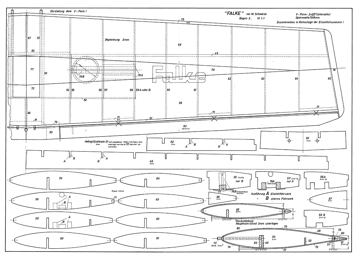
Start by gluing the main spar from parts 59 and 50 and attaching the selected plywood undercarriage reinforcements from the corresponding ribs. Including the auxiliary spar 52, the ribs 53 to 65 are fitted onto the spars, aligned and glued in place. Align and glue the root ribs 66 and 67. Then add the upper sheeting from 68 to 70. Remove the wing from the slipway and convert the latter to the negative V-shape of the upper wing surface. Place the wing with the planked upper side on top and underlay the end strip with an auxiliary strip. The auxiliary strip has a height of 17.5 mm for rib 53 and a height of 13 mm for rib 65 (see profile sections). Now attach the hinge reinforcements 71 and the rear planking 72. Carefully align and glue in the retaining dowels 73, also glue them to rib 53!
Now fit the selected undercarriage support strips 76. Then fit the remaining planking 74 and 77 as well as the leading edge 75. Make and glue the edge bows to the 15 mm thick balsa according to the profile at rib 65. Then attach the aileron drives 79 and the end strip pieces 80 made for them. After sanding, glue on the plywood reinforcement 81. The ailerons 82 are made from a symmetrical end strip (30 mm x 15 mm). Sand the wing, especially the leading edge and trailing edge, cleanly according to the profile. For reinforcement, laminate an approx. 40 mm wide strip of glass fabric with epoxy resin over the center of the wing.
The wing support of the fuselage must now be checked and adjusted exactly to the finished wing. If necessary, the retaining holes in frame 9 must be adjusted to fit the wing dowels 73. Finally, it must be possible to screw the wing to the fuselage at a precise angle to the tailplane. To increase the support on the fuselage, a 0.8 mm or 1 mm thick, approx. 10 mm wide plywood strip can be worked into the fuselage side panels 1 and 2 and glued in place.
Surface treatment
Everyone has their own method here. Foil covering is particularly easy and time-saving. More work, but also a more attractive model, is achieved by impregnating with pore filler, covering with paper and then painting.
Rudder hinges
The ailerons and rudder are each attached with 3 hinges, the elevator with 4 hinges to ensure stability and a central position.
Installation of the radio control system
It depends on the components intended for installation. An experienced model builder will have his own method here anyway.
Center of gravity
This should be balanced according to the plan in conjunction with the installation of the radio control system. This should be done in such a way that no additional trim lead is required.
Rudder deflections
Aileron +/-15/12 mm
Elevator +/-25/25 mm
Rudder as much as possible
Specifications:
Wingspan 1,55 Meter
Lenght: 1,59 Meter
Recommended drive: 10cc two-stroke
Flying Weight: ca. 3,5 kg
This airplane is for sale:
https://www.umfc-kirchschlag.at/marktplatz/marktplatz.php?mp_Aktion=detail&mp_Segment
Drawings (please entlarge image, I have the original plan as a PDF)
