
When processing the photos of the T.O.C. 1976, Phil Kraft’s beautiful aerobatic model ‘Super Fli’ immediately caught my eye. Years ago I had already worked extensively on a scale replica of this beautiful aeroplane design, but unfortunately the project came to nothing due to illness. Here is the article from MAN March 1976, supplemented with our photos and the scaled-down construction plan of the original aeroplane.
Here is the original report from Model Airplane News at the time: Dan Lutz built the scale Super Fli and is a modeler from the old school. Dan is equally adept at Peanut Scale, Free Flight or Radio Control and is also a meticulous restorer of old cars. lt is not surprising therefore that his model of the Super Fli is truly beautiful, and except for the lack of a pilot’s head, it is difficult, if not impossible, to distinguish from the largo Super Fli in the air.

Flying the model Super Fli is an exhilarating and refreshing change from boring Pattern airplanes. In my over 20 years of flying Radio Control, 1 have never flown another R; C model that I enjoyed as much. The R IC Super Fli is a snap-rolling fool. lt is the first model with which I have been able to do successful Lomcováks over and over.

Lomcovák is an outside snap roll entered from an upward line which terminutes in an end-over-end tumble. It’s a very violent looking maneuver, but actually isn’t at all hard on the pilot because once the aircraft snaps, the G-forces are unloaded, and it is then an easy end-over-end tumble.

With the model Super Fli a Lomcovák can be entered either from a 45° upright climb or from the same angle inverted. With plenty of power and speed, it can be made to tumble twice which is quite a spectacular maneuver.

White the model Super Fli is primarily great at the type of spectacular maneuvers displayed at air shows, it is also capable of precision flying. I don’t mean to imply that you should attempt to compete on an equal basis with an FAI contest airplane in the FAI Pattern, but you could certainly do the Pattern well and it would be a lot more fun.

Although the all-up weight of the model is over 9 lbs., the Kraft .61 has no difficulty in pulling it through all maneuvers. So far I have done no experimenting with props, but the 13.6 used seems to do an outstanding job.

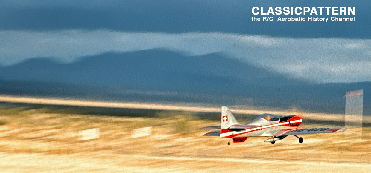
To date, the model has only been flown from our dirt field, and, therefore, I can’t comment on the ground handling. lt is excellent, however, on dirt. lt seems to inherit the good directional stability of its big brother.

Of course, it’s not a beginner’s model because the landing gear tread is quite narrow, and it can be a handful in crosswind landings. Also, in flying, things happen very quickly with this type of air-craft, so reasonable caution should be exercised during the initial test flight.

Dan Lutz designed the paint scheme, and 1 think that it is largely responsible for the pleasing appearance of the Super Fli. Dan has written some notes regarding his construction of the Super Fli, so if you want to build a scale model that puts flying fun back in R C, read on.

CONSTRUCTION. The fuselage is a basic-box type of assembly with stringers added over the sheet balsa sides and stringers on the bottom. The fuselage sides should be medium weight, straight-grained 1/4″ sheet as well matched as you can find. Use 1/16″ plywood doublers as shown in the side view of the plans.
Glue the 1/8″ x 1/4″ uprights to the inside of the fuselage sides. Be sure to make a left and right side. Join them together and use the cross section drawings for correct widths of the top and bottom cross braces. Add the 3/8″ balsa flysheet to the outside of the forward sections of the fuselage, then the stringers and corner strips.


Glue the 3/32″ plywood to the rear face of the cowl. Note that the air exits on each side of the cowl are wider than the front of the fuselage. The entire cowl is covered with medium weight fiberglass cloth. lt also has an extra layer on the bottom half of the in-side for added strength. Two cam locks and three locating dowels hold the cowl in place.
The engine mount box is made from 1/4″ plywood with hardwood corner gussets. Coat the entire engine compartment inside and out with resin to fuel proof it.
The landing gear is bent from 5/32″ piano wire except for the center V-strut which is made from 1/4″ piano wire. Silver solder the wheel pant attachment plates to the main struts. The landing gear fairings are made from balsa sheet. Leave about a 3/32″ gap between them and the fuselage sides. The wheel pants are made from soft balsa. The fairings and wheel pants are covered with medium weight fiberglass cloth. Make sure the wheels turn freely in the finished pants.

The final assembly and alignment of the parts should be checked carefully. Note that the stabilizer is set in at a slightly positive position as shown on the side view. If the fuselage sides and doublers were cut out ac-cording to the plans and the stabilizer is located as shown, you should have 1° to 1-1/2° decalage balance no farther back than 28% of the wing core (this is 3-V2″ from the leading edge at the fuselage).
The open areas of the fuselage are covered with silk. The ribs in the tail sur-faces are simulated with 3/32″ white trim tape just before the basic white color is applied to the model. The original model was finished with K&B Super Poxy using their “matched finish system.” A final top coat of clear Super Poxy was applied to the entire model to seal the trim tape and decals.
MODEL AIRPLANE NEWS • April, 1976

Images: Günter Hoppe, MAN, Jerry Nelson

THE ORIGINAL


Super Fli Walkaround