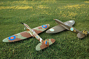
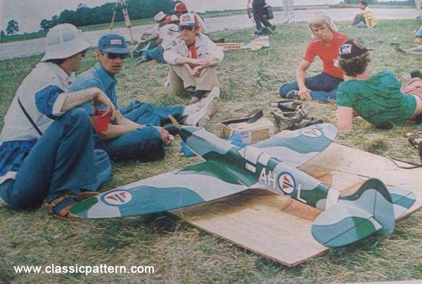
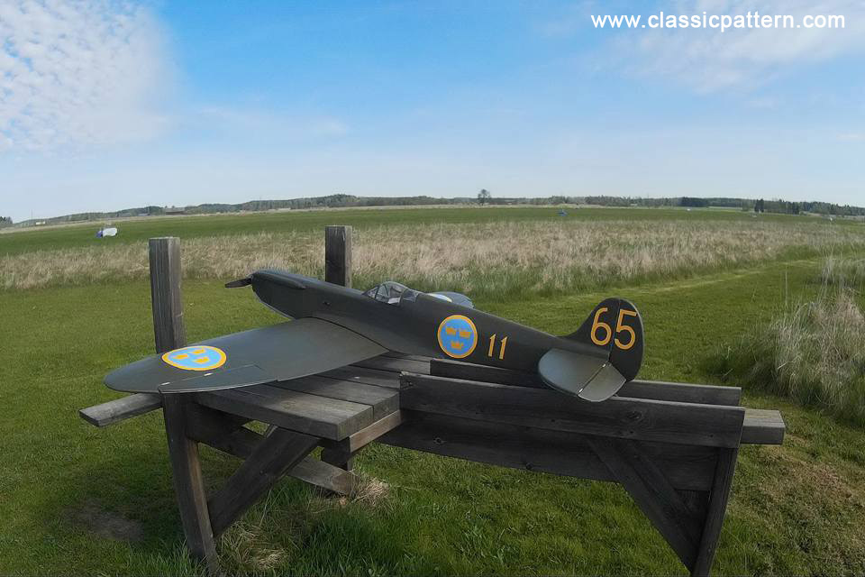
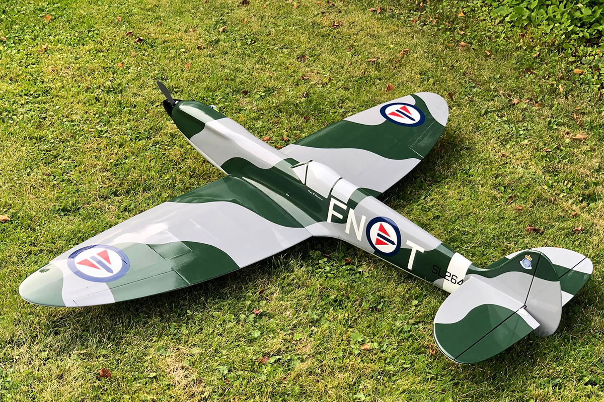
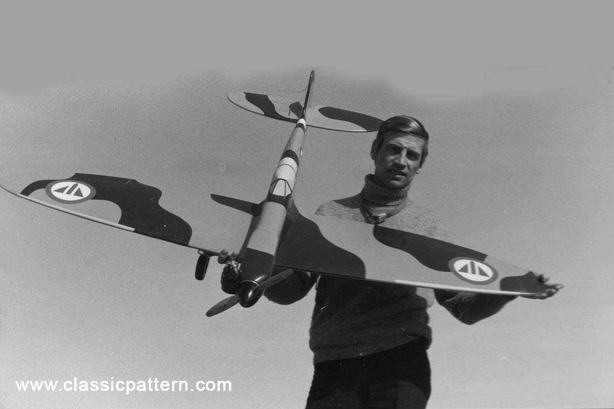
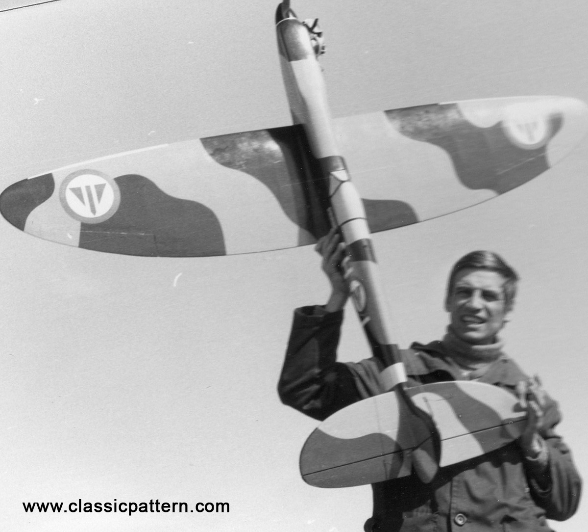
In 1975 and 1977, the Norwegian RC1 aerobatic pilot represented his country Norway at the Model Aerobatic World Championships in Bern / Switzerland (1975) and Springfield / USA (1977). At that time he had a different idea for the aerobatic model: it was to be a semi-scale replica of an original airplane. For this purpose he constructed his ‘Spitfire’. Here is the story and the construction report on the construction plan
By TORE PAULSEN . This ship was outstanding at the 1975 World Championships, both in appearance and in performance. Scale-like aircraft in precision pattern is a trend we`d like to encourage.
Pattern designs have, in my opinion, become very stereotyped. They are all variations on the same theme. I do not agree that it has to be this way, and this Spitfire is an attempt to prove that a semi-scale Model can be competitive.
Anyway, building and flying the Spitfire has given me more fun than I had for a long time. Seeing the Spitfire silhouette pull out of a high split-S and whistle by at a low altitude is really something, because this is not a slow lumbering scale model, but a highspeed pattern aircraft with performance to spare.
One of the reasons for choosing the Spitfire for this project is the elliptical wing form. It gives less induced drag than a normal wing and therefore has less tendency to slow down in maneuvers.
There are, of course, lots of other prop aircrafts to choose from . . . the ME 109 would be a natural. Likewise the Bearcat, Zero, Mustang, and several others.
There is one problem with this type of model, and that is the tail-dragger configuration. No problems on a grass field, but they tend to be tricky on a hard surface. I believe this problem can be solved by experimenting with wheel hardness, tracking, gear positioning, and tail wheel steering accuracy.
I found, for example, that putting a slight drag brake on the main wheels improved both take offs and landings, even with uneven brakes. Going to harder wheels also helped. No brake on the tail wheel though, it fouls up the steering.
This Spitfire is a second design, correcting some problems I had on the first one. It is, of course, not the last and ultimate. I guess no design will ever be.
CONSTRUCTION
The elliptical wing might at first sight scare off potential builders, but is actually not hard to build with the method described.
Mark down all rib and spar positions and set the board at 3 degrees dihedral. Cut out all ribs as described on plan and glue the jig pieces on the- jig.
Wet and bend the two spruce spar joiners to dihedral, and when dry, glue them to spars. You now have one upper and one lower full length wing spar. Make a good joint, as the main wing strength comes from these spars.
Prepare ribs for retracts, pushrods, servo Installation, etc. Pin down lower spar to jig and glue in all ribs and center section. Next add the preshaped T.E., W-10, and the inner lamination of the L.E. Cut this one slightly oversized and trim to follow rib contour when dry. Glue in upper spar. Bevel the spars at the tips and pull together, to follow the general curve of the wing. Ribs W-7 and 8 must be sanded down smoothly from the spars to meet W-10 in order to have a straight hinge line for the ailerons. Add upper sheeting, and when completely dry, remove wing from jig.

At this time, try your installations for fit. Set jig at 3 degrees anhedral, reverse wing and pin to jig. Trim L.E. and ribs W-7 and W-8 as on upper panel. Add lower sheeting and again, when dry, remove wing from jig, Glue in remaining L.E. laminations and wing tips. Sand entire wing. Cut aileron blank from light wood, tack-glue in place and shape to follow wing contour. Finally, cover center section with fiberglass.
The rest of the construction is conventional, and only a few points will be mentioned. Cut out fuselage sides and ply doublers. Glue together with polyester resin. It makes for a good and warp free bond.

Build fuselage upside down on a flat building board. Plan all your installations when the basic box is finished. Next, add nose block, upper block, aft turtle deck and bottom sheeting. Trim fuselage to shape before adding canopy.

Put Saran Wrap on wing center section and bolt to fuselage. Build up wing fillet from micro balloons or similar material. Make stab and bolt to fuselage, while checking for 0-degree incidence in relation to wing. Then epoxy in place. Glue on fin and fair into fuselage and stab with soft balsa.
To avoid flutter, make control surfaces light and stiff . . . use straight pushrods and no sloppy linkages. I used nylon cloth hinges on ailerons and klett hinges on rudder and elevator.
My engine is a Webra Speed 61 F with a special HP carb. Use a good’ mount, like Fox, and position the engine as close to the firewall as possible. The’ RST 12 oz. slant tank is pushed in, sideways, right up to the firewall, with the outlet facing the fuel tubing exit hole in fuselage.

The vent line is connected to the muffler pressure tap. The tap must be around 3/32 I.D. to give good steady pressure. Use a large volume muffler, at least 100 cc, to reduce back pressure. The Minivox Super Silent is good. Prop and spinner must be balanced. Top Flite 11-7 Super M and Williams 2-1/2 inch spinner works fine.
The conversion from mm to inches on the plan is not always accurate, but this is in places where wood size is not critical.
The original model was finished in WW II camouflage colors, with’ the markings of the post war 332nd Norwegian Squadron. Refer to literature for this. A Spitfire finished in red will bring doom upon its builder!
Here is the construction plan of Tore Paulsen`s F3A Spitfire
PATTERN SPITFIRE – AMA – Academy of Model Aeronautics (modelaircraft.org)
Specifications:
Wingspan: 1,60 Meter
Weight: 3,3 kg
Engine: Webra Speed 61 F with a special HP carb
Drawing: Model Builder Magazine No.176
Many thanks to Tore Paulsen`s son Dag Henning Paulsen for the super B photos!
With the help of:
