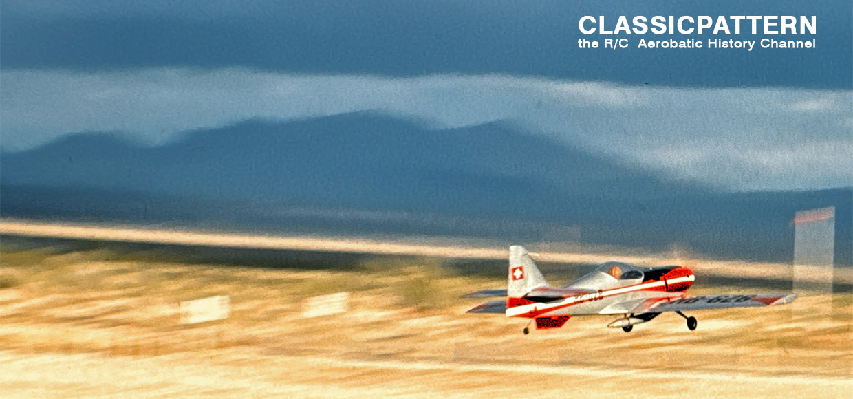
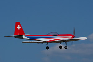
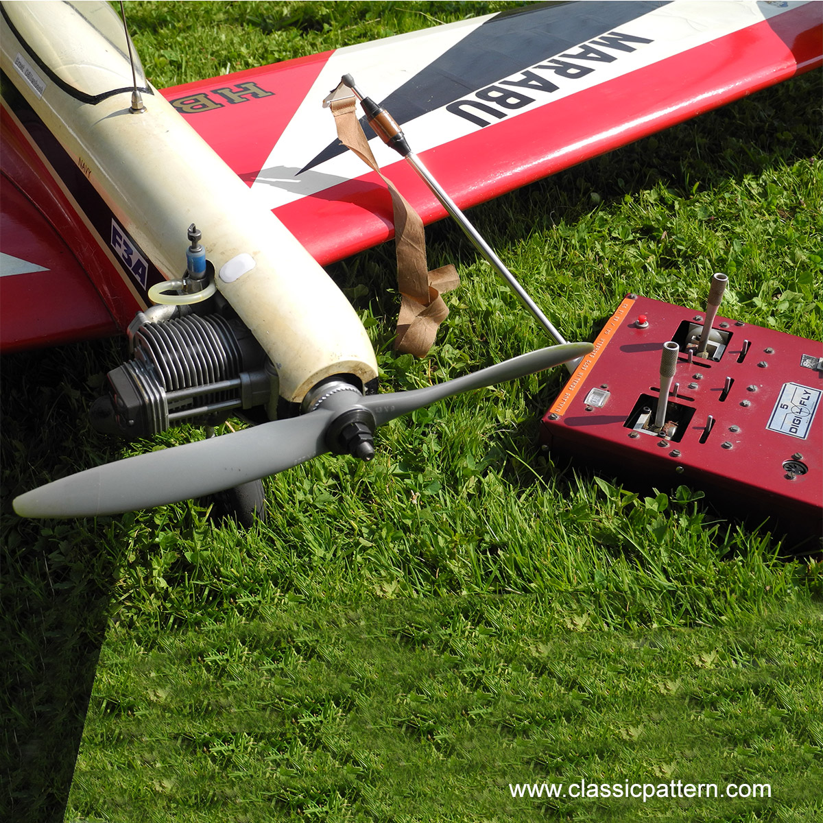
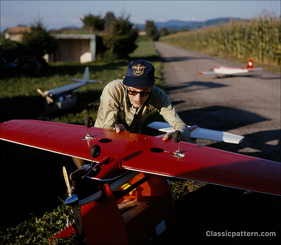
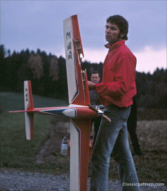
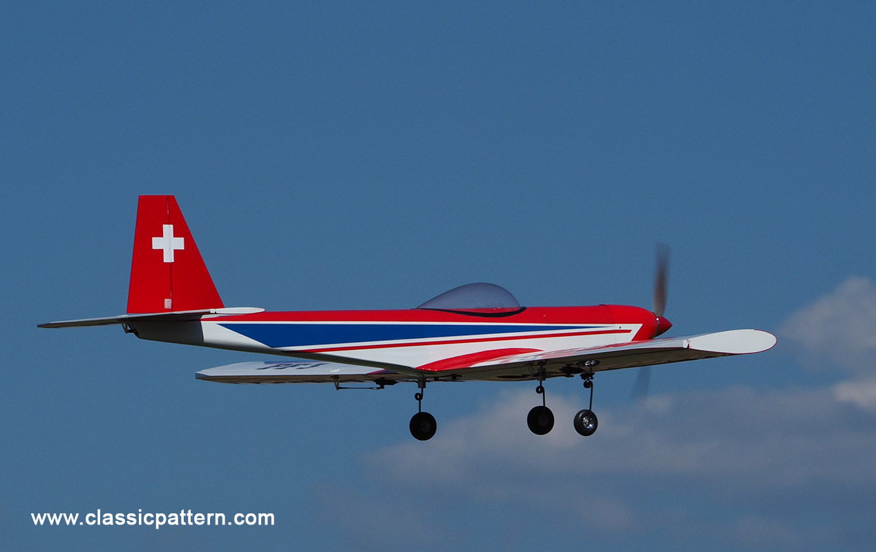
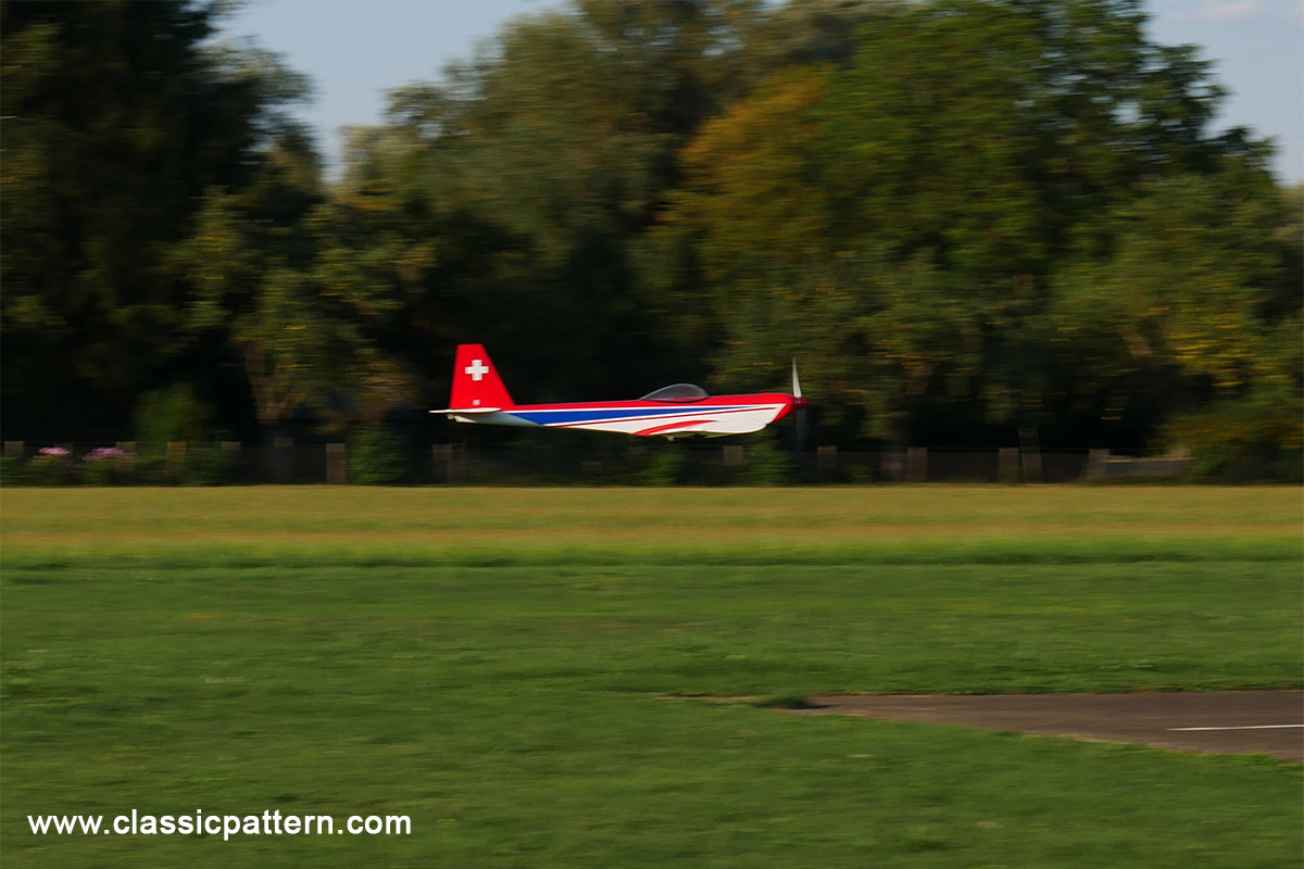
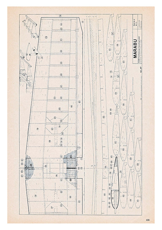
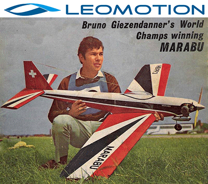
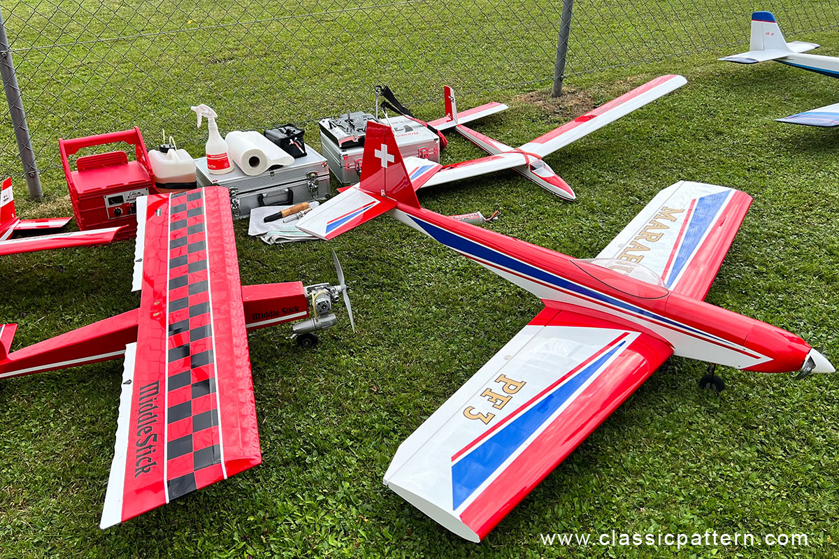
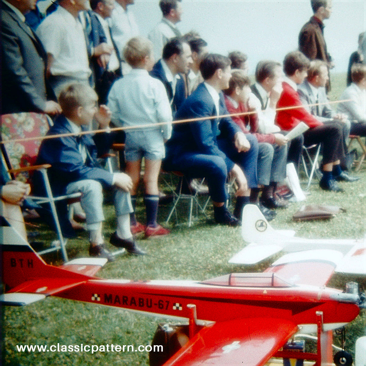
Here is the Giezendanner construction Marabu. The Marabu was used for the first time during the RC1 World Championship in Corsica in 1967. At that time the Marabu was larger than the 1967 and 1969 versions with a wingspan of 1.81 metres. Here is our photo collection of the Marabu’s, original as well as modern replicas. And the build description by Bruno Giezendanner.
The MARABU is a motorised model specially designed for aerobatics and represents a successful further development of the well-known PELIKAN. (Report by Emil Giezendanner Model 1969)

We also tried to make the MARABU simple, straightforward and easy to assemble, which is particularly noticeable in terms of labour hours.
Flight characteristics
The aerodynamic pitch and percentage profile thickening towards the wingtips, together with a very low wing loading, mean that the model is literally “good-natured” over a very wide speed range. It can be flown both at pedestrian speed and at breakneck speed.
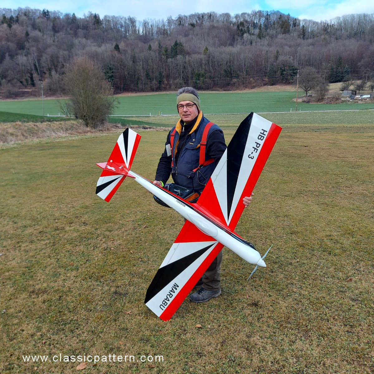
With a relatively large airfoil thickness (sensibly increased air resistance) and a favourable ratio of weight to power, we achieved that the MARABU flies at a constant speed through rising and falling figures. This is extremely important for the flight behaviour of an aerobatic aircraft.
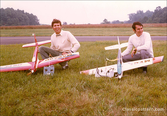
Experts only fly “hot” things?
Anyone who is passionate about aerobatics – not just on a Saturday before a championship – knows how much the quality of the model contributes to the success of each individual figure. Of course, an expert will be able to do a decent manoeuvre with an average or even poor model, but he will certainly succeed in doing significantly more manoeuvres with a good model out of a hundred than with any flying prosthesis. That’s why the best is just good enough for aerobatics.
The opinion that the model contributes one third and the pilot two thirds to the success seems more than bizarre for this reason and always reminds me of the question of which came first, the chicken or the egg, whereby I am also not quite sure what this “percentage calculation” is supposed to justify?
Model aircraft unusable for aerobatics or a lack of flying skills? The more difficult and imprecise a model is to fly, the more random the figures become. A good aerobatic pilot, however, is characterised by uniformity in the notes. The randomness is not aerobatics, but happens to every Sunday flyer – whether he wants to or not.

Aerobatic championships put a lot of strain on pilots and mechanics anyway, so everyone is happy when they know that their model turns safely, for example during a turn, and always under the same conditions. Not that he has to think about whether the model in question is design no. 7 or no. 24 and what appropriate measures should be taken for this or that type. Every competition pilot would like to spare his brain from such “cracking impulses”.

Weight and strength
The World Championships in Corsica clearly showed that a certain disillusionment with the plastic era has already set in. Moulded fuselages and foamed wings were in the minority, but they were being towed around in the air with the most powerful engines by far. No coincidence when you think of the fantastic model weights!
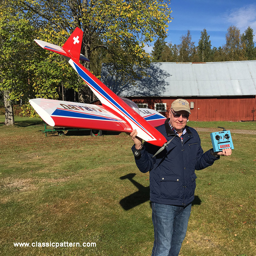
Heavy models require powerful motors. – “But the heavy lumps are less sensitive to wind.” – Corsica proved the opposite: Kraft, Marrot, Bauerheim and Spreng actually flew quite well with their relatively light models, didn’t they, or did all four of them have the good fortune to always have less wind than the others, despite swapping the starting order three times?

And what about strength? Are plastic models really stronger than wooden constructions? Or does the sentence “energy = mass X speed” also apply to us model pilots? Think about why glider models are usually easier to identify after crashes than 5-kilo motorised models.
“We have rather oversized our model in the vulnerable areas,” a theoretical model builder once wrote. What does oversized mean? Nothing other than an excuse for the heavy construction method, which makes any reinforcement of critical areas illusory. The heavier the model, the harder the impact and the greater the destruction. No amount of reinforcement will help.
How do you build light?
The overall design of the model aircraft, as well as design details, have a decisive influence on the weight. The scales will tell you objectively whether I plank a wing completely or not. In addition, of course, there is the quality of the wood, which cannot always be judged by eye and feel, but can be judged very accurately with a letter scale.
If you build several models of the same type, with a little experience you will always be able to determine fairly accurately how you are doing in terms of weight by noting down a few empirical values. The average experience values for the MARABU look something like this:
If a retractable undercarriage is used, a generous 450 g is used instead of the specified 250 g, resulting in a total weight of 3150 g, which is still acceptable for the MARABU without any disadvantages, especially as the efficiency of the motor is improved by 15 to 20 per cent with the undercarriage retracted. Despite the additional weight of 200 to 300 g, the model’s climb performance increases.
Experience with retracts
Bruno Giezendanner successfully used a MARABU equipped with retractable gear in competition in 1967. We used to use the electric DE-BOLT retracts on the PELIKAN and, since last year, the mechanical servo-operated retracts from Klaus Dieter Horn on the MARABU. The mechanically flawless, very precise and clean KDH retracts.
Weights:
- Wings 400 g
Fuselage 400 g
Elevator 70 g
Rudder 30 g
all rudders 100 g
Body shell total 1000 g
covering and finish 400 g
Landing gear 250 g
Motor incl. silencer 500 g
Tank, push rods, fittings
and miscellaneous 200 g
RC system incl. 4 servos
and battery 600 g
Ready to fly, without fuel 2950 g
Finished model 3400 g
If a retractable gear is used, a generous 450 g is used at this point instead of the specified 250 g, resulting in a total weight of 3150 g, which is still acceptable for the MARABU without any disadvantages, especially as the efficiency of the motor is improved by 15 to 20 per cent with the undercarriage retracted. Despite the additional weight of 200 to 300 g, the model’s climb performance increases.
Experience with retracts
Bruno Giezendanner successfully used a MARABU equipped with retracts in competition in 1967. We used to use the electric DE-BOLT retracts on the PELIKAN and, since last year, Klaus Dieter Horn’s mechanical servo-operated retracts on the MARABU.

However, the mechanically flawless, very precise and clean KDH chassis has impressed us; i.e. it has various advantages over the electric one, which more than compensate for the somewhat delicate mechanical connection of the servo chassis.

The correctly installed KDH retracts is just as robust as any fixed, conventional undercarriage. The American POSI TRACT is a more recent development. It is electrically powered (individually) and makes a good impression.
However, the nose wheel version has nothing in common with a technically flawless solution and will undoubtedly need to be improved. There are also doubts as to whether dirt on the motor and limit switches could lead to breakdowns in hard use. In general, I am sceptical about anything that has to use spindles (threaded rods) to convert rotary motion into traction and thrust.
Under no circumstances would I power the electric retract with the receiver battery. The Posi-Tract seems to me to be a simple and rewarding solution for scale models, which tend to be spared in terms of flying hours. Development in this area will certainly not stand still and a reliable, lightweight and robust electric retractabs will be launched on the market. The highly developed servo technology already offers a good basis for this.
It is obvious to everyone that the electrical-mechanical part must be even more carefully protected against dirt than the conventional servos, and this is a requirement because the servos are located inside the model, while the retracts are outside.
Dirty collectors, contact discs and switch contacts could spoil any enjoyment of the retracts.
We only cover our models with paper. Beforehand, all wooden parts, wings, tail unit and fuselage are treated once with stretching varnish (nitro) and finely sanded. The paper (thickest quality), lightly moistened with an atomiser, is coated directly with stretch varnish. After applying a further coat of stretch varnish, the fuselage can be painted over with a surfacer (spray filler), also nitro-based, and then wet-sanded.
This procedure can be repeated as desired until we are satisfied with the surface. Before we now paint the fuselage with nitro colours (do not spray!), we must cover the surfacer again with a coat of stretch varnish.
If you want to keep the paint job particularly light, it’s a good idea to mix stretch paint with nitro paints and, after two or three coats, give the wing the necessary impregnation and paint it with a nice base colour at the same time. In addition, one must not forget to coat an engine model with a fuel-resistant, colourless synthetic resin varnish (two-component varnish).
Emil Giezendanner
Marabu New Version 2023
Specifications:
Wingspan: 1,69 Meter
Weight: 3,2 kg
Recommended drive: 10cc 2stroke engine
Photos: Peter Erang, Burkhard Erdlenbruch, Emil Giezendanner, Urs Leodolter
