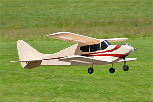
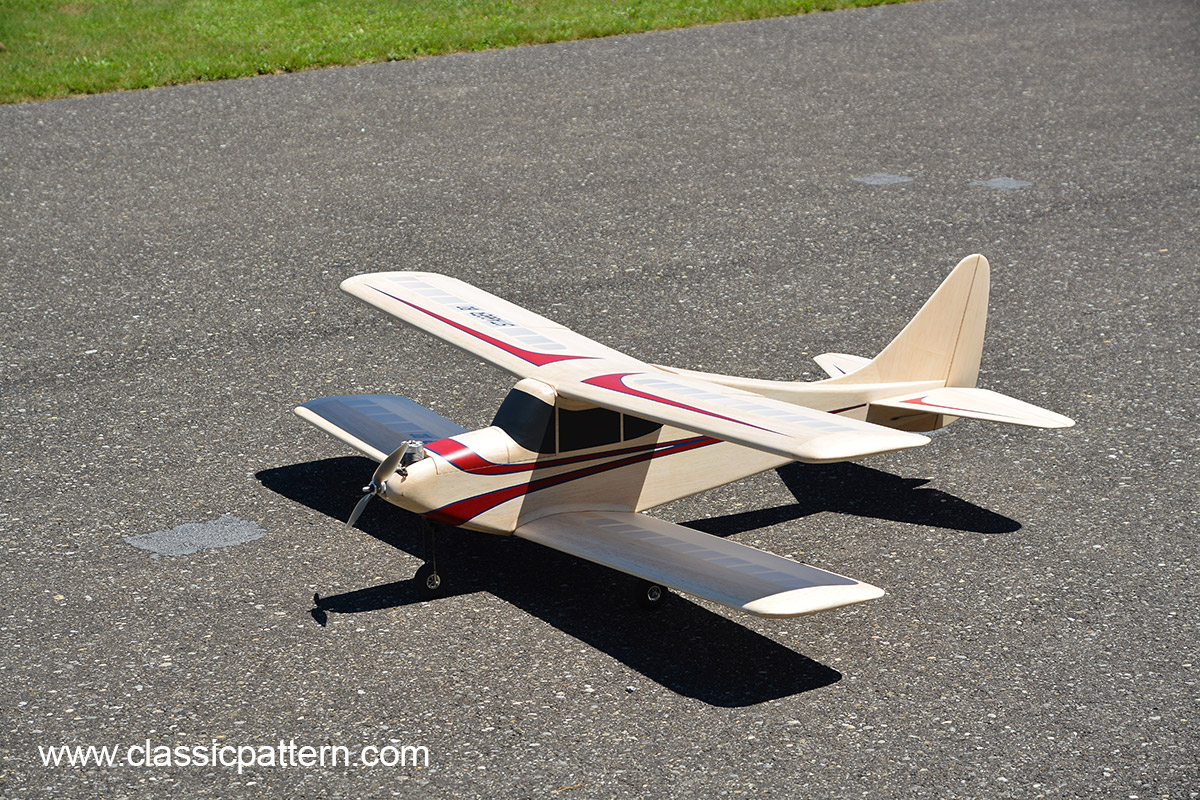
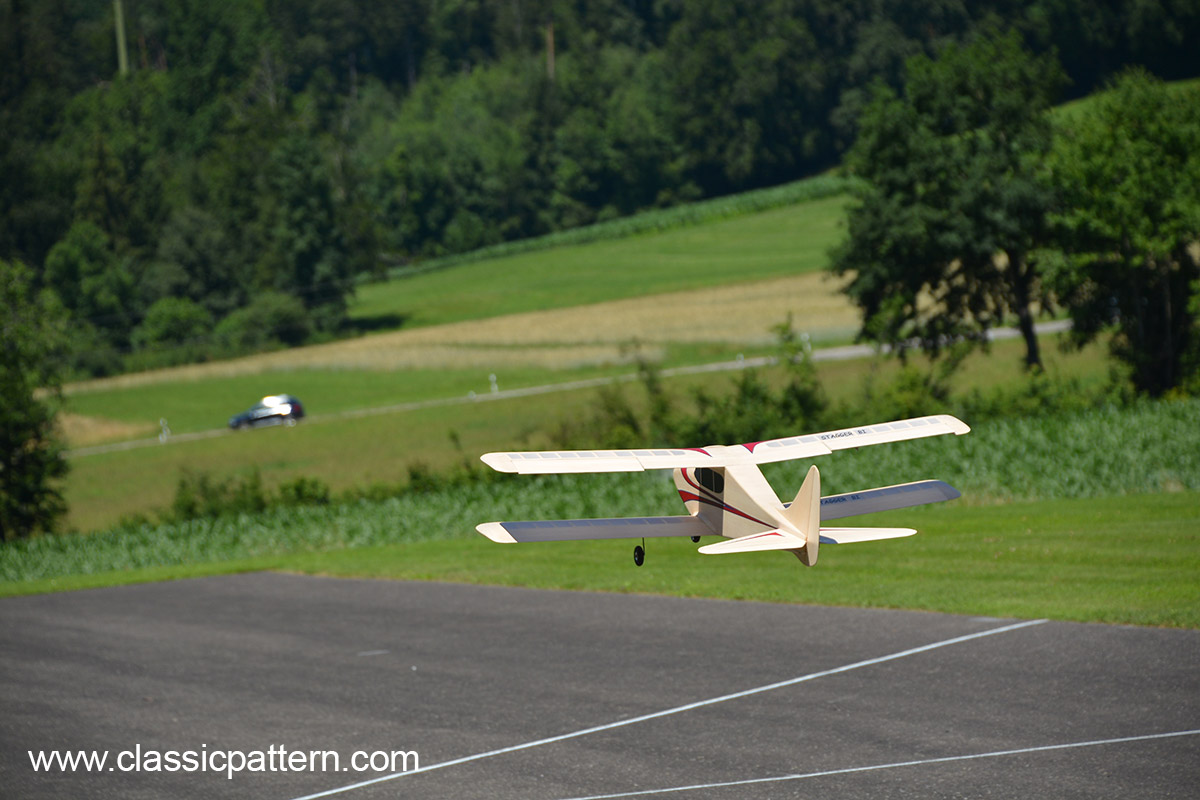
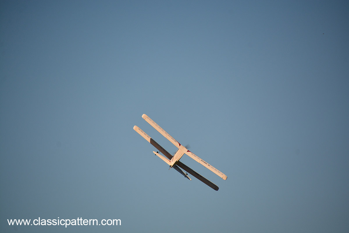
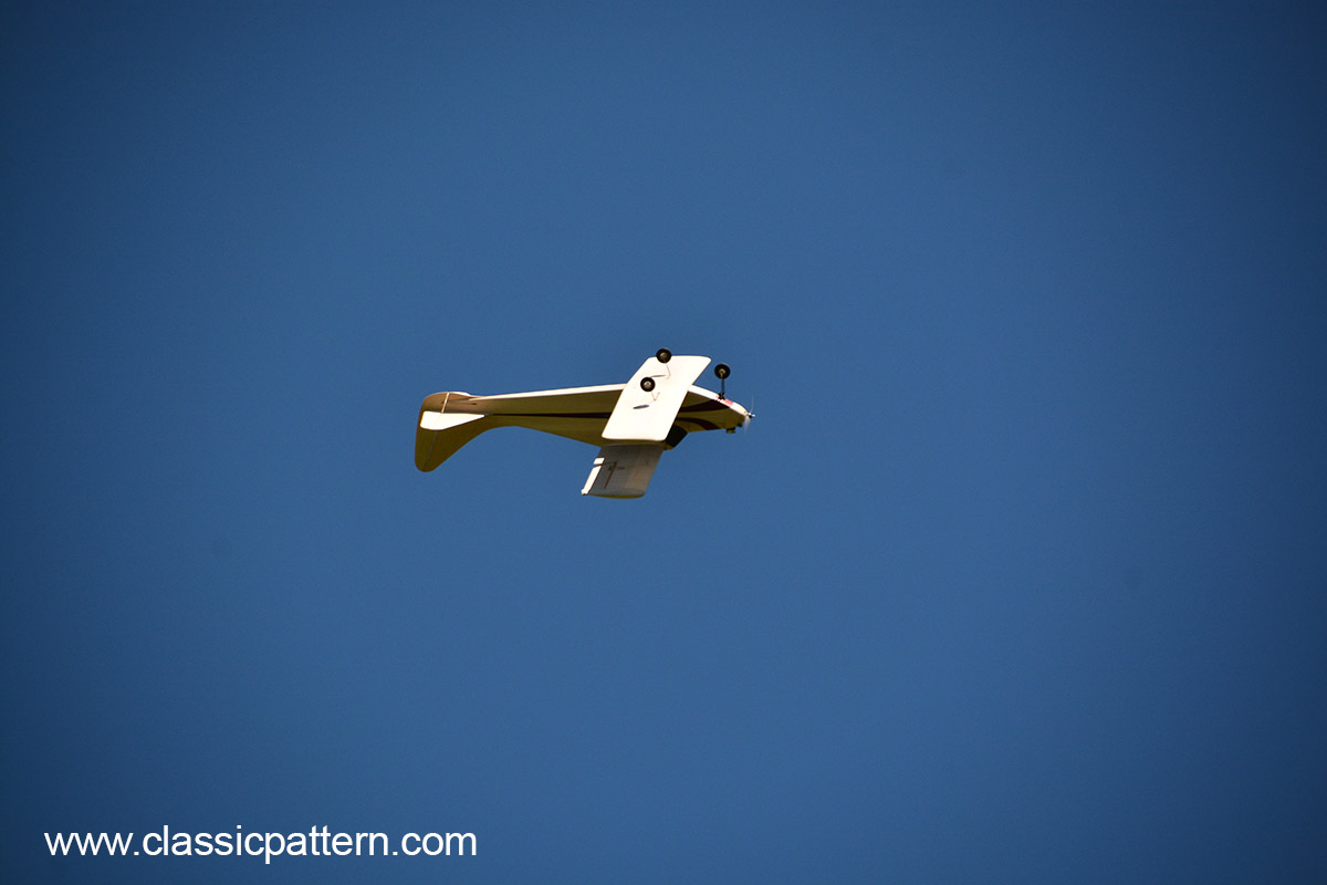
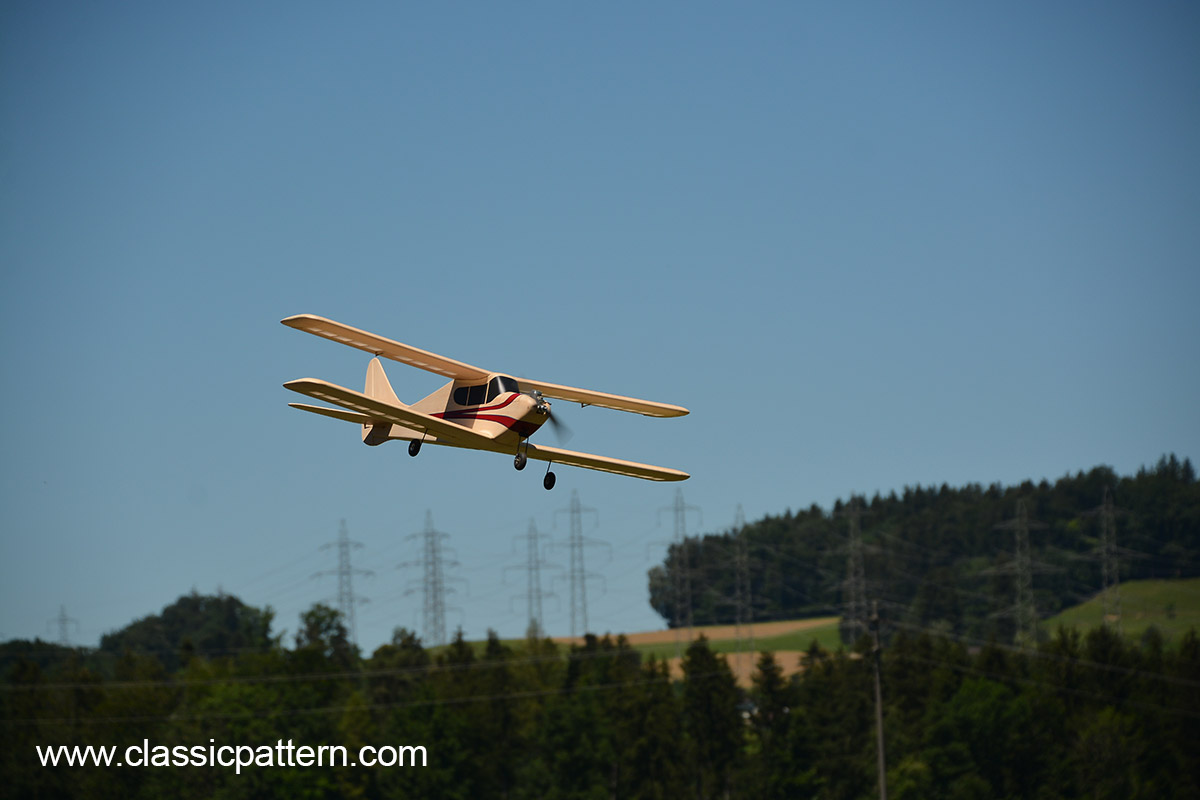
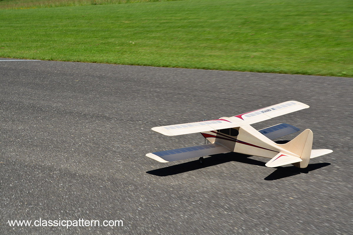
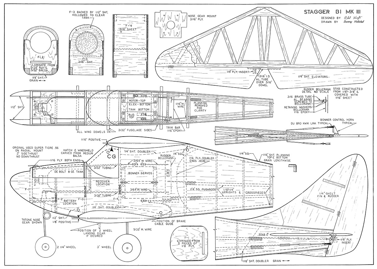
RC-I aerobatic biplane “STAGGER” from Phil Kraft USA. This model aircraft, built according to the construction plan, is ideal as a new retro model aircraft. You will impress your colleagues. Beautifui Multi-Bipe for Vintage Enthusiasts.
For many of us, the biplane evokes a feeling of nostalgia for the early days of aviadon. Although certainly obsolete for full-scale use, the biplane still has a definite place as a radiocontrolled stunt aircraft. It has the advantages of compactness, light weight, and extreme maneuverability, In addition, we can absolutely guarantee that when flying the Stagger -Bipe, the spectators will pay little attention to any other model on the field!
The first Stagger-Bi was flown in the Summer of 1959. It was a success from the beginning: very fast, highly man-euverable, and exceptionally spectacu-lar in the pattern. Two years ago, a cleaned – up version was built, adding the tricycle gear. This is the ship shown in the picture.
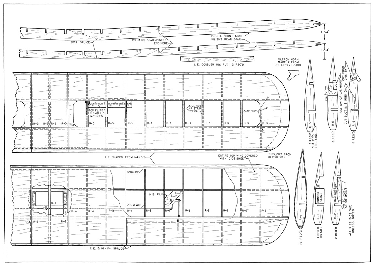
The plans show a considerable am-ount of modification in structure over thatused in the original Stagger-Bi. The only drawback to the original was the tendency for the surfaces to develop warps due to the open-frame type of construction. Since the ship is extremely fast, this made it difficult to trim for all maneuvers during the Initial flights.
Due to it’s speed and extreme man-euverability, the Stagger-Bi is definitely not recommended :or the less experienced. For this reason, and since the plans are well-detailed and self-explan-atory, only a few construction notes will be given.
Begin fuselage construction by cutting the 1/16″ ply doublers and 3/32″ sheet sides to shape. Be sure to cut notches in the doublers for bulkheads F2, F3, F4, plus servo mounts and tobe for rudder bellcrank. Glue the doublers to the fuselage sides. Glue the 1/4″ square corner longerons to each side and the 1/4″ x 1/8″ uprights to the sides and stab doubler. See the rudder bellcrank detail and assemble accordingly. Glue Fl, F2, F3, F4, nose wheel mount, ser-vo mounts and rudder bellcrank assembly in place. Install the 1/4″ sheet wing doublers and the 1/2″ sheet nose doublers to one side. Glue on other fuselage side and let dry. Tack glue cowl and hatch blocks in place. Carve blocks roughly to shape, then remove and hol-low out. Note that each end the hatch is covered with 1/16″ ply. Glue cowl block permanently in place. Cement rear of fuselage together and install cross pleces. Install nosewheel, servos, trim bar, pushrods, throttle linkage, etc. Flank top and bottom of fuselage. Note that bottom planking between F2 and F3 is 1/8″ sheet, while 1/2″ sheet hollowed to clear the nosewheel is used between F1 and F2.
Engine selection is entirely up to the builder. The ship pictured has had virtually every popular type of RC engine installed a hot Fox 59 provided the most spectacular performance. The ship is setup for a radially mounted engine which makes it possible to quickly interchange the power unit.
Since engine mounting plates are not usually standard, lt is necessary to make one to suit your particular engine. These are merely sawed from 1/8″ thick aluminum and drilled to match the four crankcase cover retaining bolts. In add-ition, drill 3 holes for the mounting bolts.
We suggest you use #6-32 nuts & bolts to mount the engine to die fire-wall, and also double-nut the bolts to avoid their loosening from vibration. After this is accomplished, remove the engine and all equiiment The fuselage is now ready for sit_iing and doping.
The wing should offer no particular problems, and can be built in two hal-ves. Cut the wing spars and assemble over the plans„ Secure the front spar in place, dien block the rear spar and fasten in place. Lift from the jig or board and sheet the leading ,and trailing edges on the bottom side.
Note that the Top Flite landing gear mount is to be sneeted over and a slot cut for the gear. Build the other wing half in the same manner. Install center ribs, landing gear mount, servo rails, bellcrank platform and sheet center sections. Leave the bottom of the wing center section (top wing) open for servo mounting. Build the ailerons separately. Cover the top center of the top wing and install ailerons. Complete the alleron linkage and cover bottom of top wing.
The stabilizer is self – explanatory. Cover the top with 1/16″ sheet before removing from plan. Turn over and sheet the bottoni.
The elevator is cut and shaped from 1/4″ medium balsa and joined with 3/16″ I. D. aluminum tubing over a sec-tion of 3/16″ dowel. Secure the tubing and – dowel hinge to the elevator with pinking tape.
The lin and rudder are cut to out-lines shown. Do not omit the stiffener in the fin.
The original Stagger-Bi had several coats of redbutyrate dope with gold and black trim, 1f light balsa was used throughout, the finished weight should be between 5 1/4 and 5 3/4 pounds.
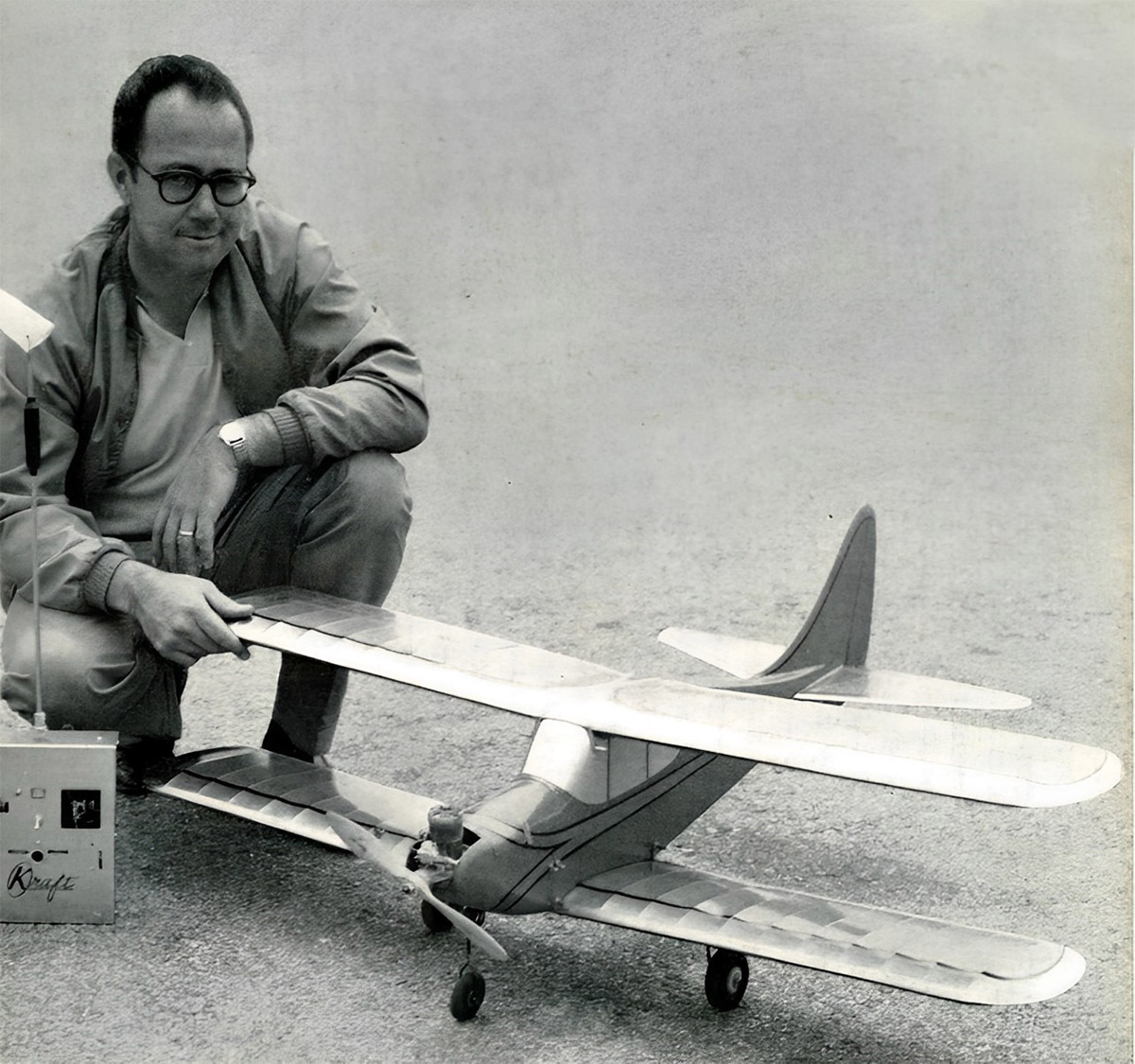
Flight trimming is quite conventional, however it is important that ‘die decalage setup of the wings be very close to that shown on the plans. The ship is not overly -sensitive to CG placement, bat it is desirable to come as close as possible to the position shown.
Some readers will be interested in the contest potential of this particular design. It has been successfully flown for hundreds of flights without incident, using both reeds and proportional control, and we feel that, properly con-structed, the Stagger-Bi has a definite contest potential. The ship does all maneuvers well. It is, however, very fast, which makes it somewhat less of a contest aircraft by the current standards of the larger and slower ships seen in today’s rneets.
We think you’ll like the Stagger-Bi—–in the hands of a capable pilot, it is always the star of die show!
Nowadays, the model aircraft is ideally suited for electric propulsion with 3-4 S Lipos.
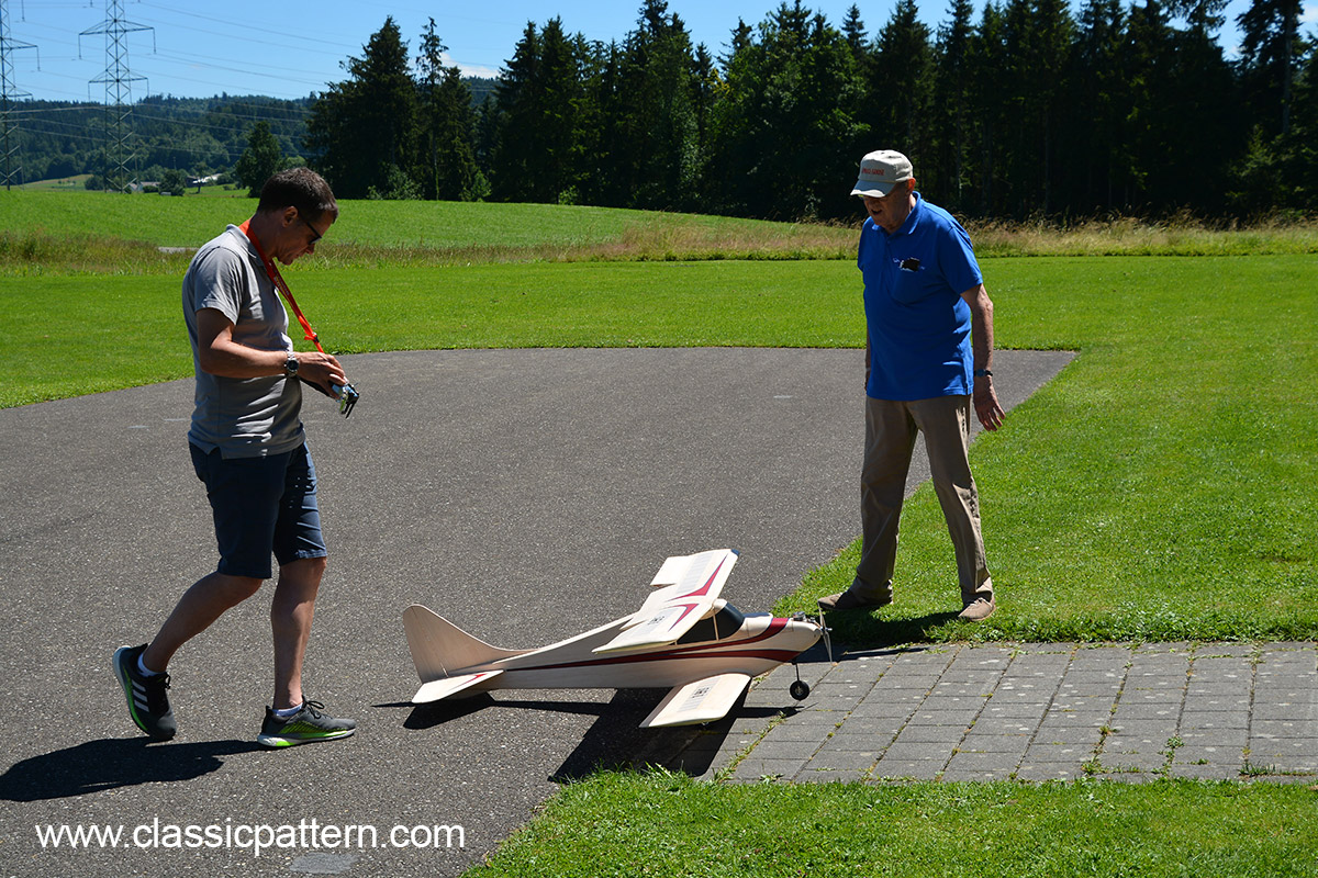
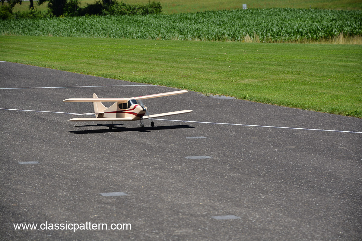
The beautiful ‘Stagger’ shown here was built by our Swiss friend Guido Patrocini and flown by Urs Leodolter.
Images: Burkhard Erdlenbruch
Text: Phil Kraft
