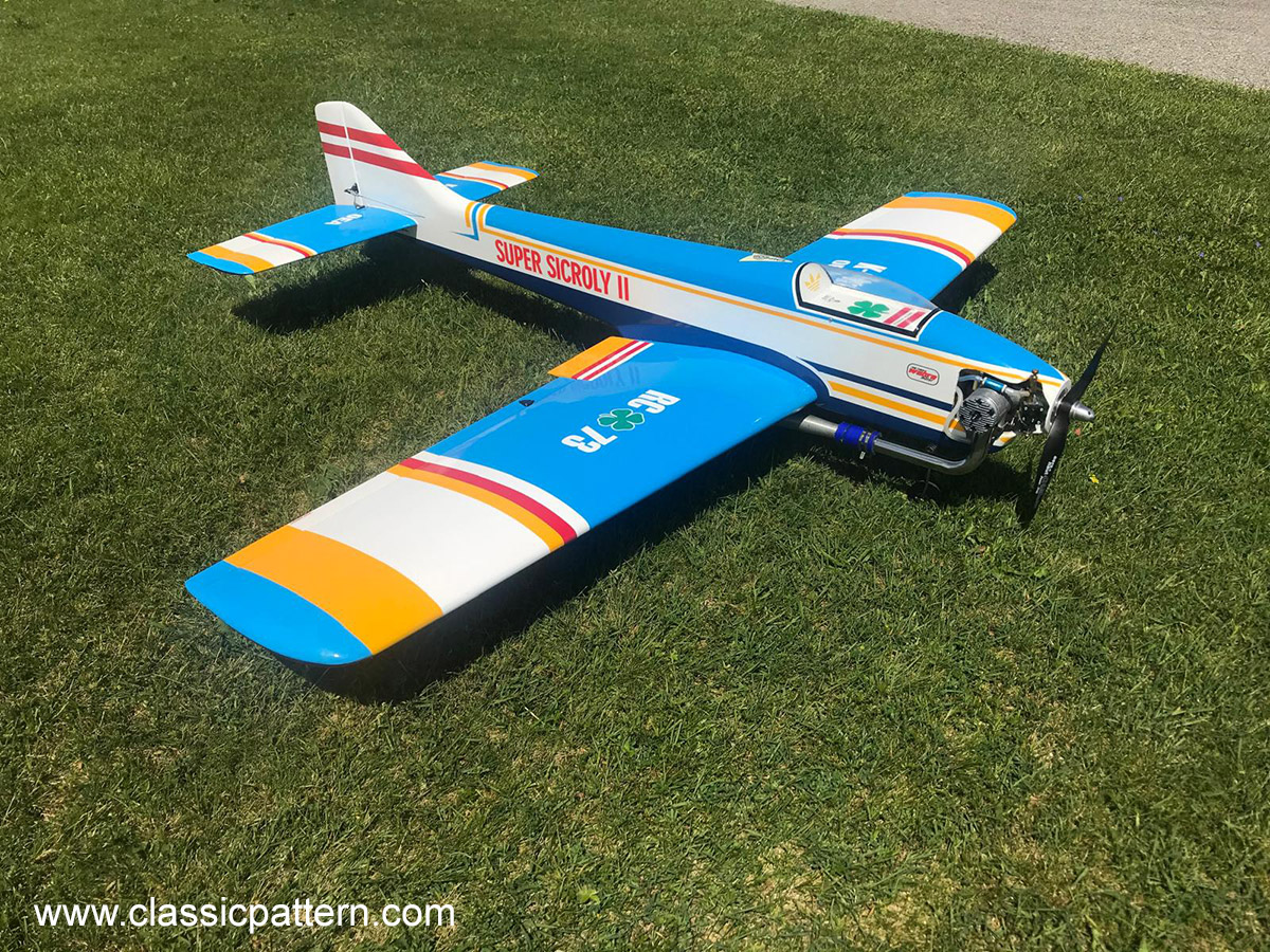
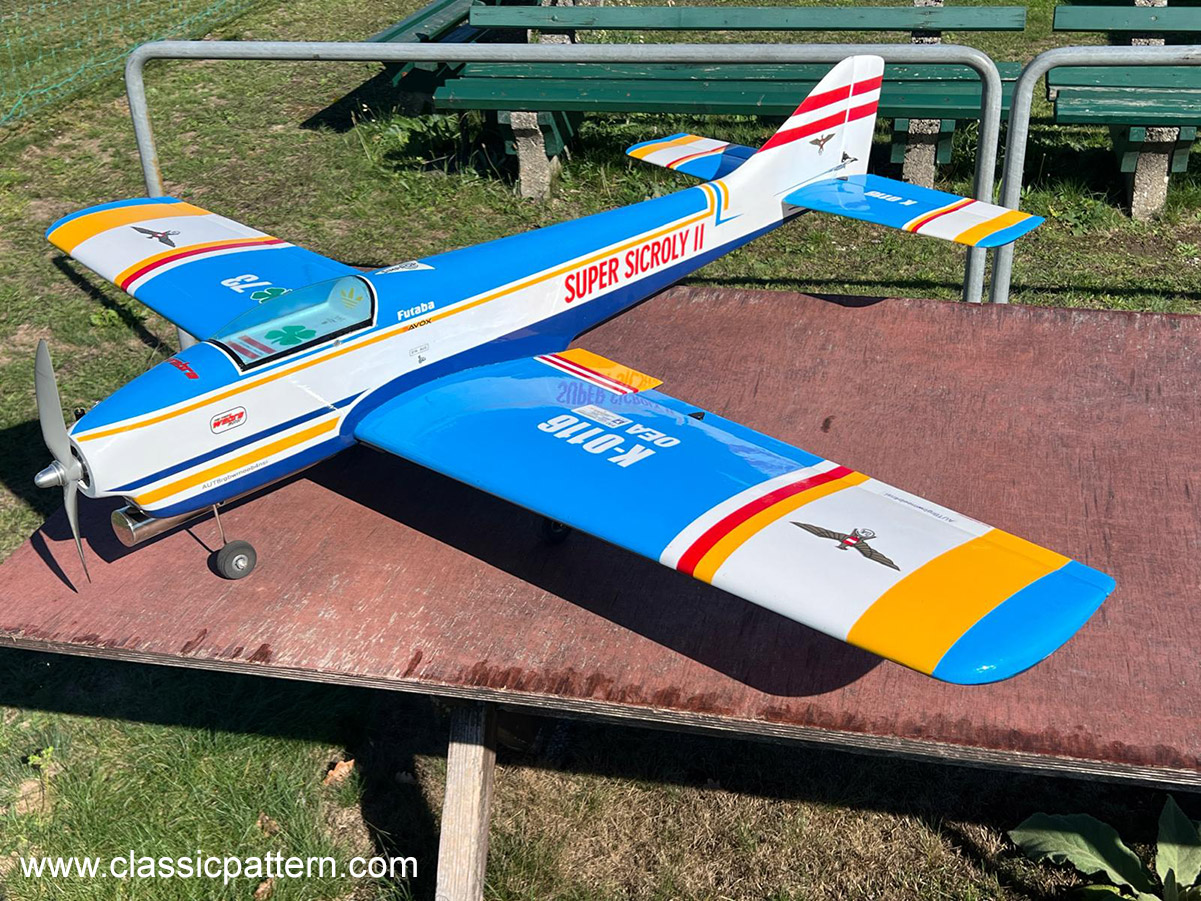
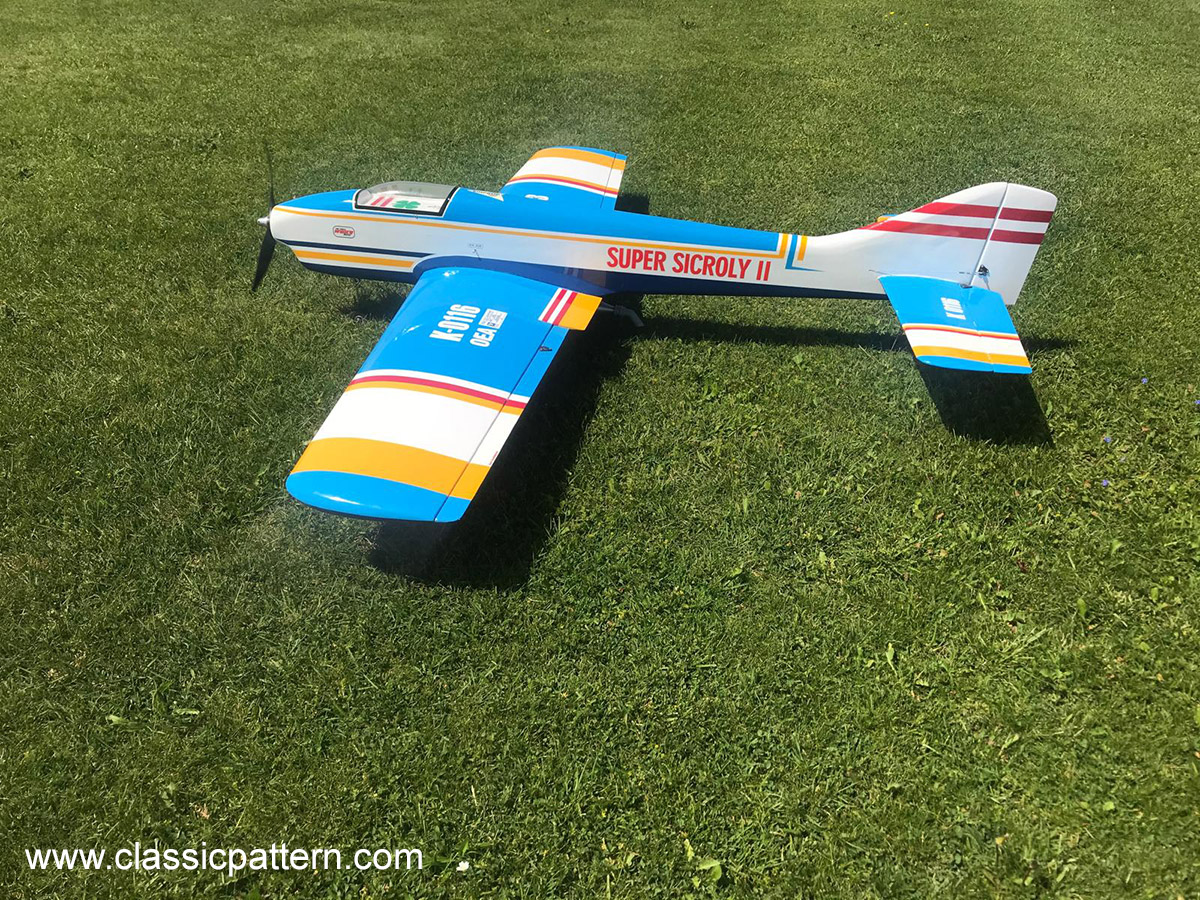
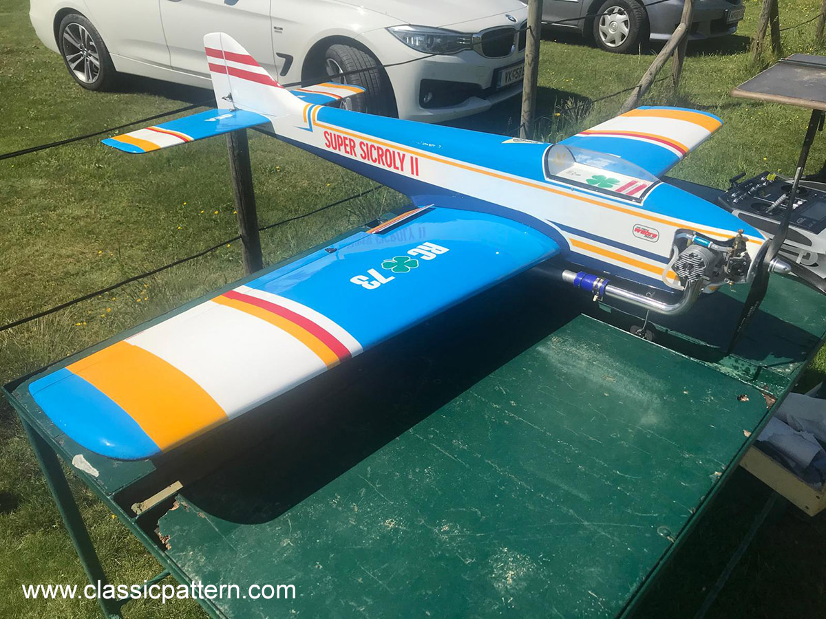
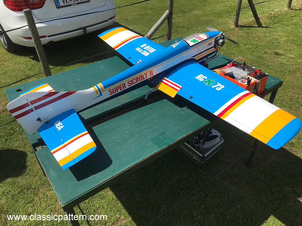
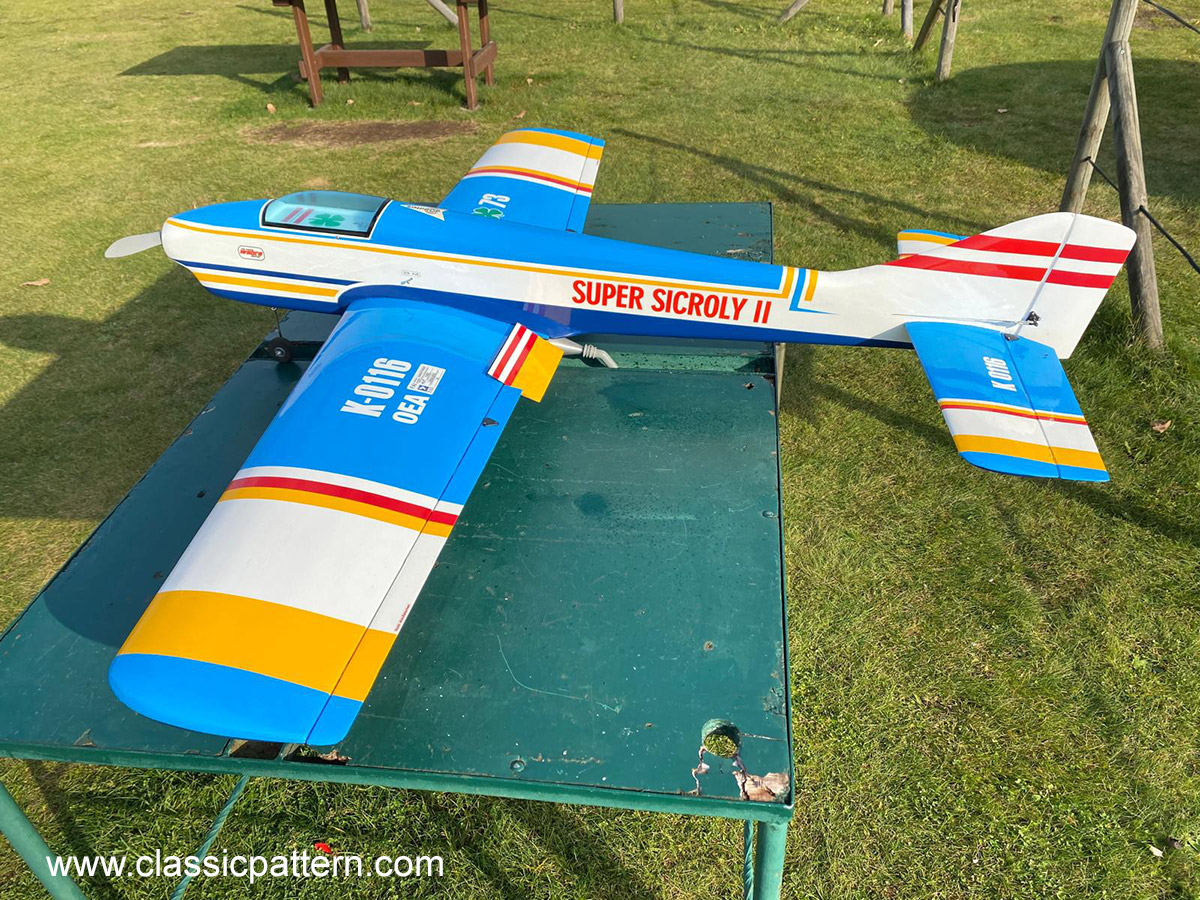
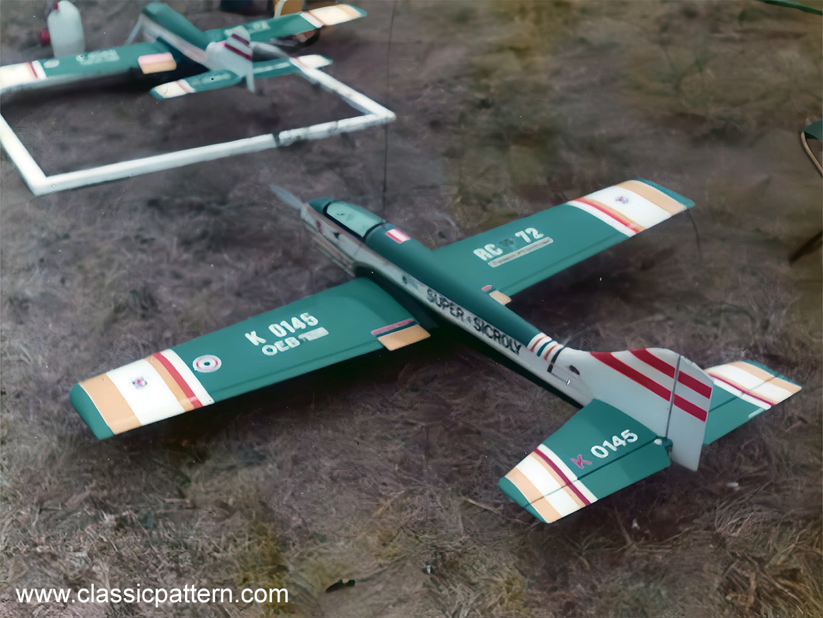
Austrian Gerald Zikulnig is an enthusiastic model builder and especially a convinced Hanno Prettner fan. He now owns several Prettner constructions. Among other things, he built a beautiful ‘Super Sicroly II’ which I present to you here.
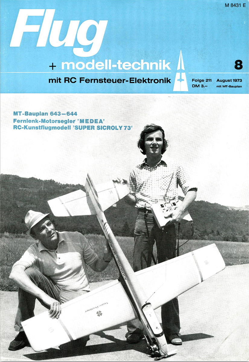
Including the article published by Hanno Prettner in the August 1973 issue of Flug Modell Technik Magazin.
Here is the report:
The Super Sicroly II World Championship model was specially designed for the FAI aerobatics programme. After the successful performance at the 1971 World Championships in the USA (4th place), I modified some of the model’s essential details to improve its flight performance even further.
It should be noted that motor power is an important factor in knife-edge flight. That is why the model is also designed for more powerful engines, although it is perfectly possible to fly with less hot engines. The landings of the model are downright fantastic; it can be landed with fully pulled elevator at about the speed of a glider model. There is no need to fear that the ‘Super Sicroly II’ will abruptly lose power; all it does is nose down and, at worst, swerve a little to one side.
Despite these absolutely good-natured flight characteristics, I would not advise a beginner to fly this model, as there are certainly better, i.e. more suitable models with which you can learn to fly. In the hands of an experienced competition pilot, however, the ‘Super Sicroly II’ becomes the terror of the competition, because it can be flown extremely accurately in the figures, which also makes it largely insensitive to crosswinds, as every gust can be controlled immediately. Incidentally, make sure you have a retractable undercarriage, as the ‘Super Sicroly II’ was already designed in this way in its first version – as the ‘Sicroly’ – and only then can it fully utilise its aerodynamic advantages.
Building instructions
As already mentioned, the ‘Super Sicroly II’ is by no means intended as a beginner’s model; the construction plan, on the other hand, is designed in such a way that any model pilot with some building experience will immediately be aware of the construction method. The only important thing is that you adhere exactly to all angles and dimensions and do not try to make reinforcements and improvements to this model on your own initiative.
Fuselage
Make sure that the side panels and the rudder are at right angles to the floor and deck boards. Since every model pilot uses a specific type of engine, the design of the engine mount is variable, which also applies to the retractable undercarriage.
I have recently started using an aluminium motor mount (which is attached to the motor bulkhead) so that any construction inaccuracies can be corrected later by changing the side pull and the motor camber. Make sure you build a removable canopy, as you will find this construction very advantageous during installation and with the foam rubber mounting of the tank, as well as in the event of any later tank defects. Make sure the leading edge of the rudder is pointed (!).
After you have sanded the fuselage blank, insert the elevator at exactly right angles to the fuselage and the rudder. Then take a non-stretchable thread, fasten it exactly in the centre of the fuselage head and now measure to the edges of the elevator. Move the elevator until it is exactly symmetrical to the fuselage. Once the elevator has been set up and glued in, the wing is now precisely aligned. Also measure the distances on both sides between the end of the fuselage and the wing tip and between the elevator tip and the wing tip. It hardly needs to be mentioned that the centre of the wing must coincide exactly with the centre of the fuselage.
Wings
The accuracy of a wing is the be-all and end-all of a model. If you build the wing yourself using the conventional rib construction method from balsa, then pay even more attention to this than to the fuselage construction, because a warped wing is absolutely useless in RC aerobatics. I always use polystyrene wings because they have the great advantage that they are very torsionally rigid and do not warp over a long period of time. The retractable undercarriage is also very easy to assemble; I simply glue two pine mouldings into the polystyrene, to which I then attach the undercarriage. The finishing touch is a glass sleeve 15 to 20 cm wide on both sides around the centre of the wing.
Note: Sand the wing roots at an angle and glue the wing halves together exactly with a positive V-shape (45 mm on each side).
Tailwing
I recommend that you use exactly the elevator shown in the plan (with the same root profile). I have tried various versions, from extremely thin to super-thick profiles, but I have actually had the best experience with this elevator. Under no circumstances do I recommend using a so-called board elevator, as the flight performance will be very poor. – I also use polystyrene to build the elevator.
Finish
You should always cover the fuselage with paper, as this increases the strength considerably. I always use a covering film for the wings and elevators. I also recommend covering the top and bottom of the ‘Super Sicroly II’ with different colours (e.g. light blue with dark blue), as this makes it easier to distinguish the model during flight manoeuvres.
Wings ribbed construction
It is clear from the previous instructions that Hanno Prettner uses only polystyrene wings for this successful model. As we know that quite a number of modellers still prefer the good old wooden construction method, Peter Scherbaum from Vienna has written a separate description of wing construction in this way, which is supplemented by detailed drawings.
The wing of the F3A model ‘Super Sicroly’ is already designed for the installation of a retractable undercarriage. If the model is to be fitted with rigid undercarriage, the parts of the undercarriage well and the corresponding recesses in the ribs are omitted.
A normal undercarriage bracket is installed for this purpose. The dimensions of the undercarriage bay shown are adapted to the KDH undercarriage system; if a different undercarriage is to be used, the structure remains the same in principle, only the dimensions have to be modified accordingly.
Before we start building the wing, all parts are cut out and trimmed according to the plan. However, ribs 9 to 15 are not made individually, but in blocks. In addition, the ribs 7 and 8 as well as the spar 1 are provided with the corresponding reinforcements 7a, 8a and 1a before assembly. It is best to use white glue for this, as well as for further assembly.
Once this preliminary work has been completed, we can begin with the actual assembly of the wing. – First, glue the centre rib 4 into the corresponding slot in the main spar 1. Then place the spar with the rib on a flat building board, underlay it on the outside according to the drawing and pin it in place. Then the other ribs are fitted into the recesses in the main spar and glued. Do not skimp on the glue. Make sure that the ribs are positioned exactly at right angles to the spar. Once the glue joints have set, the auxiliary spar 16 can be inserted and fixed in place with white glue. Now we must check the wing – still on the building board – to ensure that it is not warped. To do this, align the ends of the ribs exactly in a line (if necessary, underlay and tack down). The nose moulding 18 and the end moulding 19 are cut to size and butt-glued so that they protrude at least 1.5 mm above and below the ribs. This ensures that they are flush with the panelling after sanding. Here, too, a corresponding underlay is used to adjust the two parts to the correct V-position. The filler pieces 20 are then cut from a 1.5 mm thick balsa board and inserted between two ribs. Make sure that the boards are flush with the ribs at the top. Small inaccuracies can be levelled out later by carefully sanding over the underside before applying the lower planking. While the filler pieces are drying, we can glue on the top chord of the main spar, the pine moulding 2. Before planking, it is carefully adjusted to the contour of the ribs with a balsa plane and a sanding block so that the planking lies correctly. Parts 17, 21, 22 and 23/24 must now be fitted before the top of the wing can be planked.
This is also done on the building board. If you are not too keen on keeping the weight of the finished model low, you can also use a full-length balsa sheet. However, if the wing is finished according to the building plan, we first apply the end vane and the parts between the main spar and the leading edge.
Only then is the surface closed in the centre. Now we need to give all the glued areas enough time to dry properly. It is best to leave the wing on the building board overnight. When it is dry, so that it can be removed from the base without risk, the second spar webbing 3 is inserted on the underside. It is adapted to the profile contour before planking, just like the top spar 2. Until we can work with the freshly glued-on spar, we glue on the edge bow 31.
In the meantime, the undercarriage bay is also completed. First we fit the base plate 26 into the recesses in the ribs. Then the parts of the frame are positioned exactly vertically according to the building plan. Make sure that the boards protrude a little beyond the profile contour, as they will later be sanded with the panelling. Finally, insert the two support strips 27. Then the frame of the wing can also be planked at the bottom, after which you must wait until all the glue has hardened completely. Once this is done, the finished wing is carefully sanded
For visual reasons, we give the recesses for the wheels a circular shape. Now all that remains is to insert the dowels 25 and attach the ailerons.
We use ready-made aileron strips available from specialist dealers and the corresponding connecting wires, which are inserted into the groove in the rib 5 and in the filler piece 23 and covered with a strip.
The wing is now ready for covering. An iron-on plastic film works best, but it can also be covered in the conventional way with silk or paper.
Flying in
Check the position of the centre of gravity with the landing gear retracted. Then look at your ‘Super Sicroly II’ from behind with the radio control system switched on.
Make sure that all control surfaces are exactly neutral. The amount of deflection can be kept small, as this model responds very well to the rudder. If the remote control is in order and everything else is working properly, you can take off with complete peace of mind. If you now adjust the undercarriage so that the nose of the fuselage points slightly upwards, the model will take off flat at the end of the runway with a very slight deflection of the elevator.
To check the motor pull, pull the model up into a turn. If it breaks out on one side, the motor pull should be moved one track (‘/2 to 1 degree) to the other side. Repeat this until the ‘Super Sicroly II’ climbs straight up to the turn. If the model then breaks out to one side during the loops (negative or positive), add some lead to the lighter half of the wing. Once the ‘Super Sicroly II’ has been flown, all control surfaces must be set exactly to 0, otherwise a construction error may have crept in.
So much for my notes on this model. – With a little luck and a little training, you should soon be successful in competitions with this top model, and I am sure that you will then build the “Super Sicroly II” more than once.
Installation and use of landing flaps
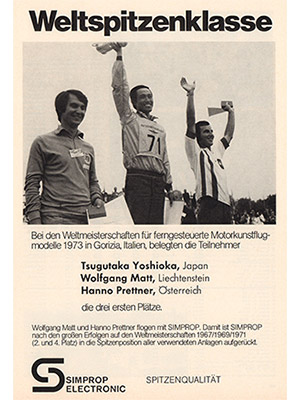
In Gorizia Hanno used his ‘Super Sicroly II’ with combined brake and landing flaps.
Hanno Prettner writes:
“The advantage of these combined brake and landing flaps is not only the extremely slow landing speed, but also the fact that you can use these flaps at any time in flight without having to change the elevator trim. So if you extend these flaps at full throttle or idle, the ‘Super Sicroly’ flies at exactly the same angle of attack. Special care must be taken to ensure that the flaps move exactly synchronised, for which it is best to use a linear servo.”
Specifications
Wingspan: 1600 mm
Length: 1385 mm
Engine: 10 ccm
Remote control: Multi-channel system
Weight: 3400-3600 g
Text: Hanno Prettner / FMT
Pictures: Gerald Zikulnig, FMT Redaktion, Ehsti Katzi


