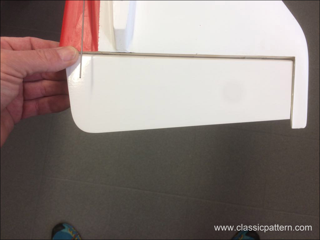
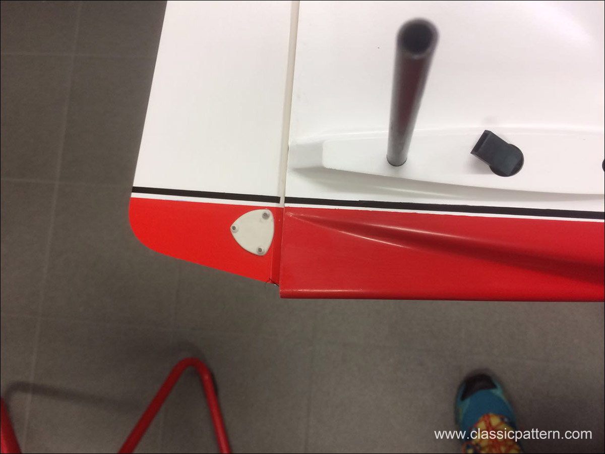
These are the special parts supplied for the electric version:
All Information About Vintage Aerobatic Planes


 3, RC1 WC 1963 Belgium
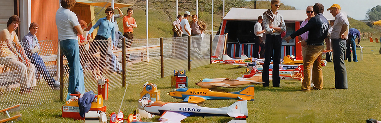
Third World Radio Control Championships To Genk, Belgium, on August 21st, came thirty-nine competitors and a great many more “followers” […]
 4th RC1 World Championship 1965 Sweden
A piece of contemporary history – a comprehensive documentation of the 1965 World Cup in Sweden with lots of details […]
 5, RC1 WC 1967 Corsica
In our series of past RC1 (F3A) World Championships, our aim is to document as accurately as possible all the […]
 FAI World Championships Reports
The World Aerobatic Championships have been held since 1960, organized by the FAI, Model Flying Section. Thanks to our consistent, […]
 13, F3A WC 1983 USA
Hanno Prettner (Austria) won the 13th World Championships for Radio Control aerobatic model aircraft in Pensacola, FL an October 10-15. […]
 12, F3A WC 1981 Mexico
This report is about the F3A World Championship in Acapulco, Mexico. Thanks to Phil Stevens and Gerard Werion for the […]
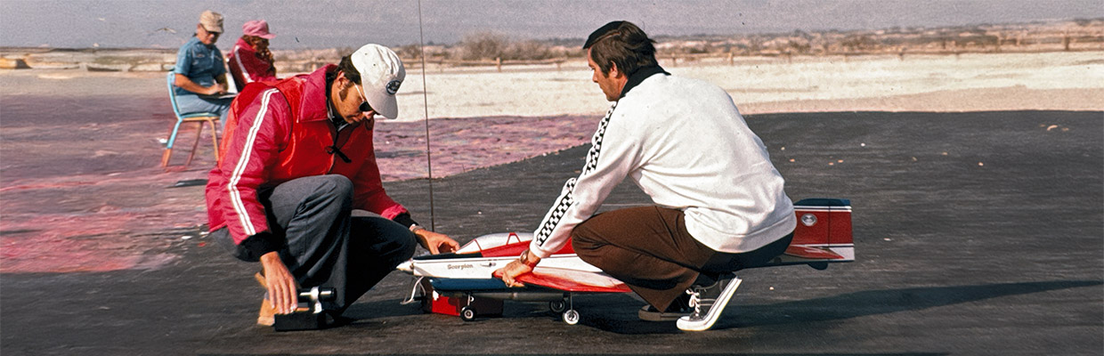
 7, F3A WC 1971 USA
World Aerobatic Championships, USA 1971, a report by the well-known German RC author Erich Rabe at the time. I remember […]
 14th F3A World Championship 1985 Netherlands
Here is the report of the 14th F3A RC Aerobatic World Championship in Flevohof / Netherlands. Ernst Peter Kattelmann was […]


