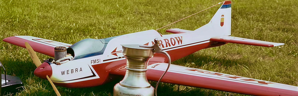
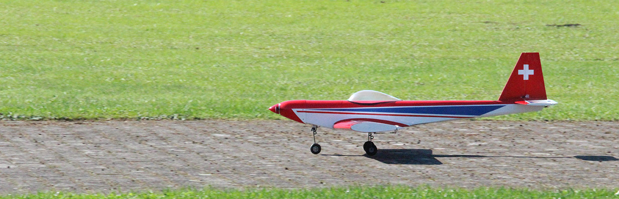
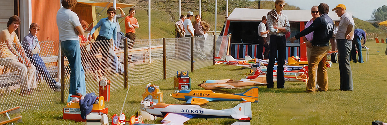
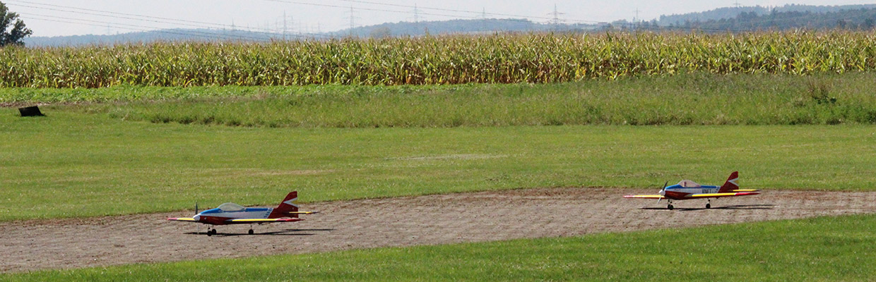
Finally, I present the Giezendanners’ aerobatic trainer design. There are two aircraft in this new replica series: one is flown by Urs Leodolter, and the other is flown by me. After winning the F3A World Championship title in 1969 in Lemwerder/Bremen, Bruno Giezendanner and his brother Emil decided to develop and build a Marabu trainer.
Here is the original report by the Giezendanners from 1969 in Modell Magazinen. The photos show several Marabu trainers, including the original Marabu trainer by Bruno Giezendanner and my replica of this beautiful trainer.

Following the release of the Marabu, which Bruno Giezendanner raced in Lemwerder with a slightly modified hull and went on to become RC 1 world champion, we are particularly pleased to be able to present his latest model to our readers today.
MARABU TRAINER
by Bruno and Emil Giezendanner
Do not expect a completely new type of aircraft with new flight characteristics. This time, I cannot present you with a retractable landing gear, nor can I invite you to play with De Havilland flaps. I do not have laminar profiles for balsa wings and rearward-mounted “ailerons” to offer.
As you will now realise with some disappointment, the Marabu trainer is a conventional shoulder-wing aircraft whose flight characteristics are most similar to those of the Senior Falcon and Sämann Caravelle. Along the same lines, we also find the well-known Ugly Stick (including copies), which I also highly recommend to any RC beginner.
Incidentally, the Marabu shoulder-wing model also has a lot to offer experts: it can be flown flawlessly in aerobatic manoeuvres.
If you want to use the Marabu trainer for aerobatic training, there is no way around building the model, which is made entirely of balsa wood, with extreme precision and care. If you fly a model during basic training that somehow glides crookedly through the air or exhibits other unpleasant characteristics, you will get used to something that is wrong. However, if you already have some aerobatic experience, such “sour cucumbers” can be extremely annoying.
Fuselage
We always cut the fuselage side walls from balsa plywood sheets, which we first cut to the required length. If you want to build something a little cheaper, you can cut the side walls out of normal balsa boards (3 mm) and reinforce them with okoumé plywood up to approx. 5 cm behind the wing end. The triangular straps are fixed to the side walls with steel pins or fine nails until the glue dries. The front triangular straps are glued in later.
Once we have sawn out the three plywood frames and fitted the engine frame with the landing gear flange and engine mount, we can begin assembling the fuselage. Use screw clamps to press the side walls onto the frames. Make sure that the side wall is also correctly positioned on the block in the nose of the fuselage. Before inserting the floor, the grooved hardwood block for mounting the main landing gear must be glued in place with the corresponding plywood reinforcements.
If you have carried out this work conscientiously, you will never have any problems with the landing gear. Inserting the floor and the deck boards is now no longer a problem. You can pre-round the fuselage with a plane and smooth it down with sandpaper. The nose is adjusted to the engine and spinner so that you get a nice transition.
Tailwing
The vertical stabiliser is assembled flat on a board and weighted down well to dry. The vertical stabiliser can then be lightly profiled with a plane. The rudder is cut out of a board (balsa) and sanded to a slight taper. We build the horizontal stabiliser on a simple slipway, which consists only of thin balsa strips and a straight board.
Hard balsa wood must be used for the nose and tail rails of the elevator so that the whole thing does not warp later. Inserting the ribs and planking is now no longer a problem. You can weigh down the planking so that it rests securely on the ribs. Once dry, remove the tailplane from the mould and plank the underside. Weigh it down again and sand the nose and trailing edge!
Wings
Since we use the same wing for the Marabu shoulder-wing aircraft as for the original Marabu (low-wing aircraft), you must ensure during construction that the wing plan shows the low-wing version. For the shoulder-wing aircraft, the landing gear beams are of course not required. The recess for the aileron servo must be moved to the underside of the wing. The time you spend building a precise jig is definitely worth it. If you want to switch to the low-wing version later, you can use the same jig again.

If you want to make several wings, you can nail two conical strips (according to the plan) to the slipway board instead of the rib supports shown on the plan. For the wing nose, I recommend two tried-and-tested construction methods: a) the curved, pre-formed planking (according to the plan; Fig. 1), b) the raised leading edge (Fig. 2).
Method a. The nose planking is thoroughly soaked in hot water (bathtub) and dried in a polystyrene negative. We cut the negative out of a polystyrene block using a “hot wire”. According to the sample ribs.
Method b. Push the planking against the nose bar and secure it with pins until dry. Then plane and sand the nose bar. Caution! Only use hard adhesives. If you use adhesives that remain elastic, the transition between the planking and the nose bar will not be clean.
Adhesive tape is ideal for pulling the planking tightly onto the ribs. To dry, we now have to place the wing back on the slipway and immediately attach all the planking at the top. Now you can leave the surface to dry on the slipway. The longer you can leave the wing clamped in this position, the more certain you can be that it will not warp. When you remove the wing from the slipway, you can finish planking the underside.
Cut the end ribs roughly out of hard balsa wood, glue them onto the outermost ribs and smooth them down neatly. Intuitively, you may want to round these end ribs or attach actual edge curves.
However, the angular edge rib has several advantages over the ‘disadvantage’ of high profile resistance, which only really plays a role in racing models. The advantages are: low construction costs (with maximum precision), favourable induced resistance.
Assembly
Adjusting the wing first and then the tailplane is not a matter of principle, but it does simplify many things. If you do it the other way round, you will have to grind away a few millimetres from the wing support immediately if, for example, the angle of attack difference (AAD) is not exactly correct.
However, if you align the tailplane with the wing, you will need to sand less in this case. It is important that the chord line of the outermost rib runs parallel to the tailplane chord line. In any case: slightly positive rather than negative Adjustment angle differental.
The whole thing can be easily checked by attaching balsa strips to the previously marked profile chords with pins and then checking or measuring the parallelism of these two strips from a distance of about 3 to 4 metres (of course, the strips must not bend). Once everything is correct, the tailplane is glued in place. The installation of the fin also requires great care. Firstly, it must be positioned exactly on the centre line of the fuselage and, secondly, it must be perpendicular to the tailplane.
The wing can be attached using nylon screws, Camloks or the tried-and-tested rubber bands, as you see fit. When using rubber bands, do not use hardwood dowels or the fuselage section around the wing tip so that the wing can be removed without damage.
Finish Once the shell has been neatly plastered and treated with hard primer (or pore filler), cover the entire model with strong paper (silkspan). Of course, one of the new silks or super monokotes can also be used.
After two to three coats of tension varnish (Fuller’s), the model can be “decorated” with nitro or synthetic resin paints. Spray fillers and similar products should be avoided, especially if you are a beginner or intend to use the Marabu as a training model in rough terrain.
Technische Daten:
Wingspan: 1.69 metres
Fuselage length: 1.37 metres
Flying weight: approx. 3 kg
Power: 10cc two-stroke engine
Electric drive: Leomotion 4120 610 KV
Battery: Lipo 5S
Text: Bruno Giezendanner
Images: Burkhard Erdlenbruch, Johanna Huang


