Toni Bäuerle: Ciao Kosmo! Sometime in the summer, Maurizio and I had the idea of building the KOSMO 3 model by Benito Bertolani.
Full content is available to paid subscribers only.
Support Independent Journalism by subscribing today.
All Information About Vintage Aerobatic Planes
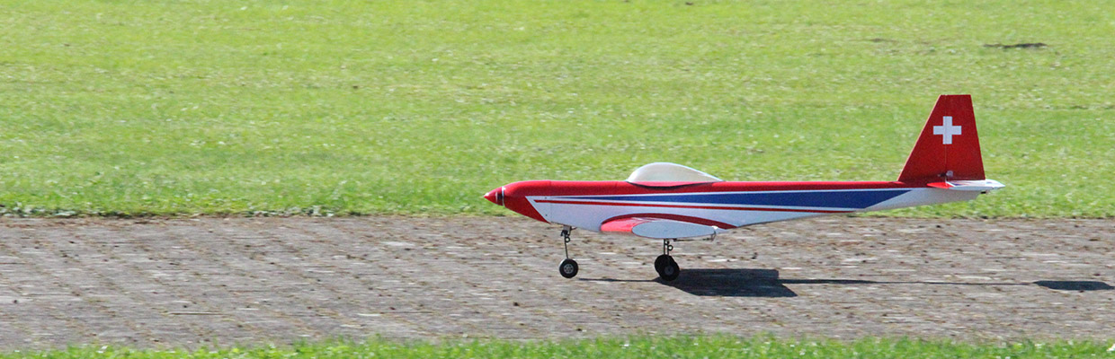
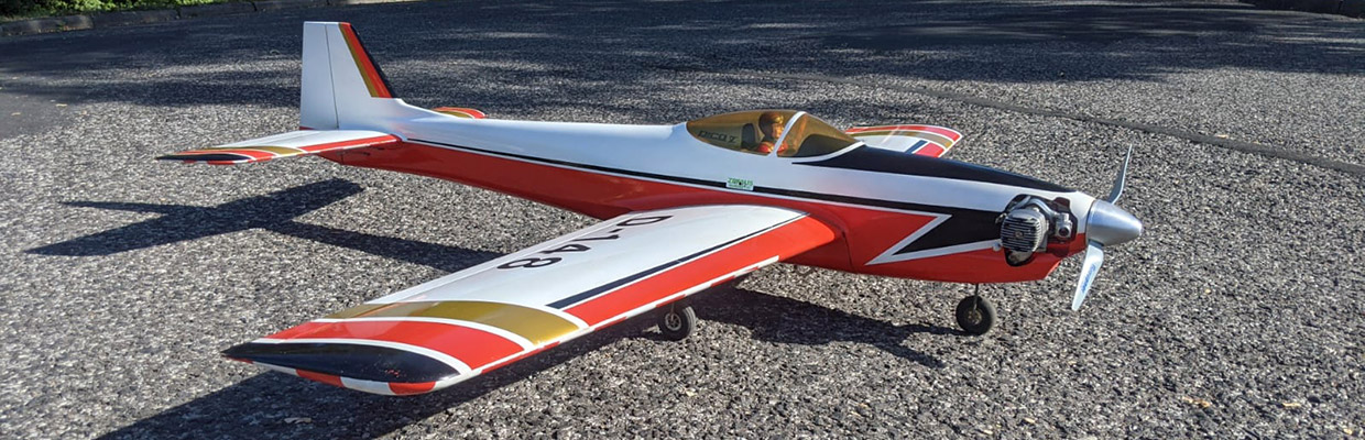

Toni Bäuerle: Ciao Kosmo! Sometime in the summer, Maurizio and I had the idea of building the KOSMO 3 model by Benito Bertolani.
Full content is available to paid subscribers only.
Support Independent Journalism by subscribing today.


 14th F3A World Championship 1985 Netherlands
Here is the report of the 14th F3A RC Aerobatic World Championship in Flevohof / Netherlands. Ernst Peter Kattelmann was […]
 10, F3A WC 1977 USA
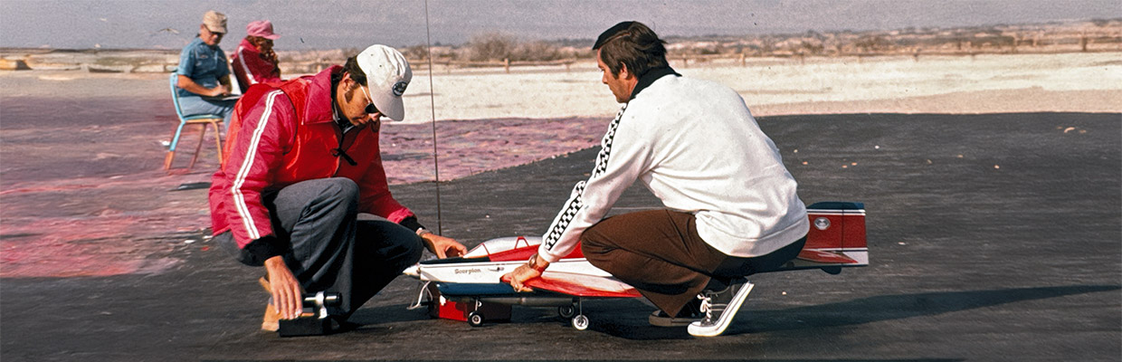
1977 was the year of aerobatic competitions. First Bill Bennet invited us to the Circus Circus in Las Vegas, and […]
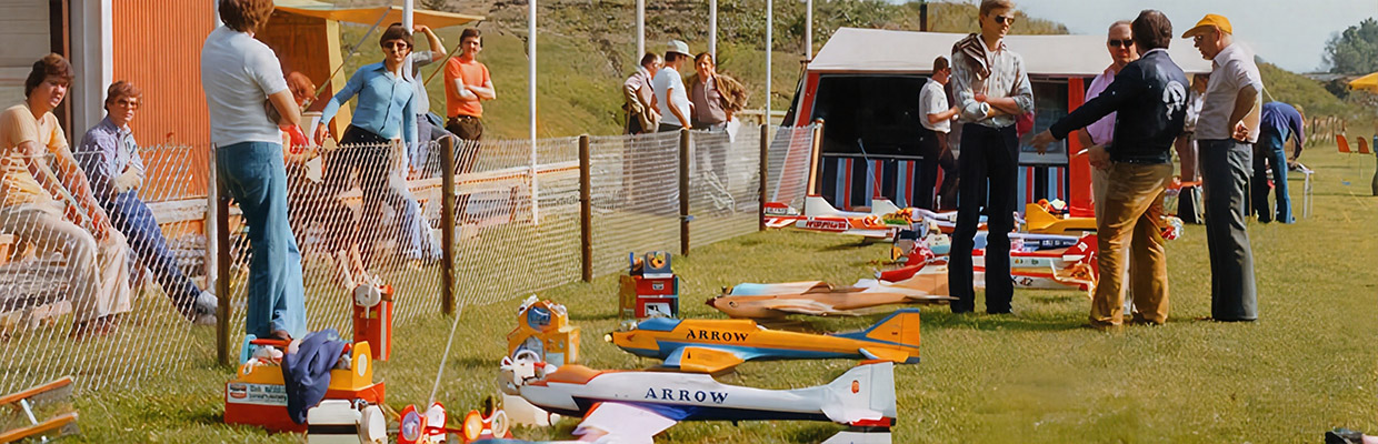
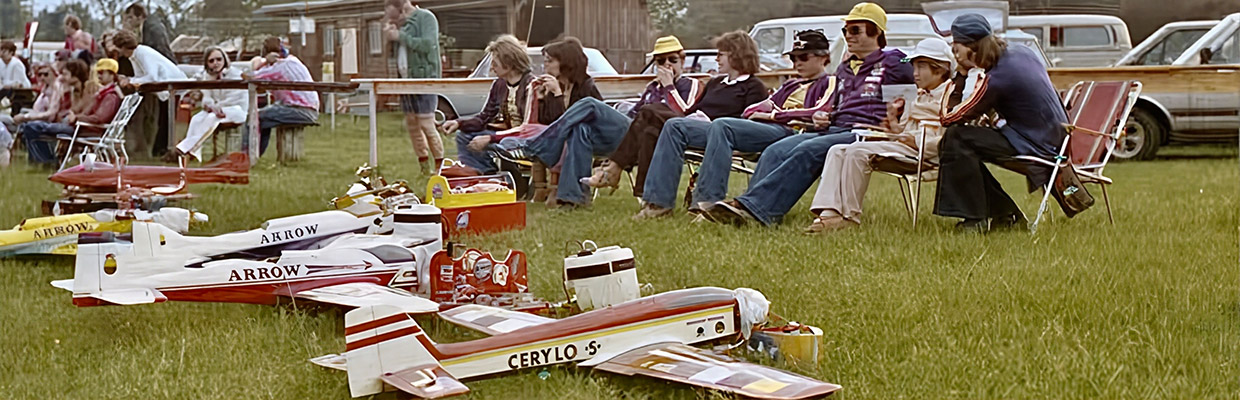
 9, F3A WC 1975 Switzerland
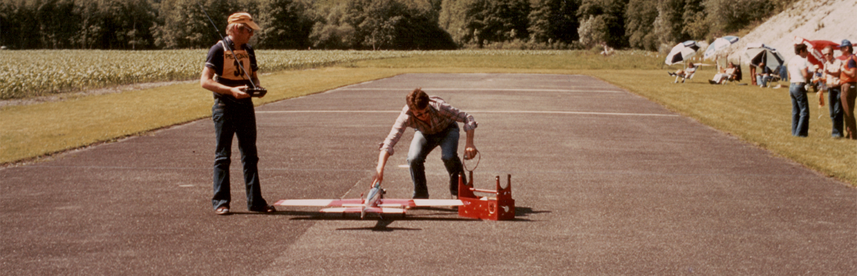
Aerobatic R/C Airplane World Championships BERN, 8.-13.Sept. 1975, THE World Radio Control Championships for aerobatic model aircraft came home for the […]
 6, RC1 WC 1969 Germany
F3A Aerobatic World Championship 1969, Lemwerder / Germany: We have revised the report and the photos. We have ‘spiced up’ […]
 15. F3A WC 1987 France
The year is 1987 – what a luck. The Australian participant, Chris White, and the Finn Ahti Yliriesto provided us […]
 11, 1979 F3A WC South Africa
Many thanks to the South African Len Salter for this terrific report, many thanks also to Phil Stevens and Gerard […]
 1st RC1 World Championship 1960 Switzerland
We have revised and updated the report on the first World Aerobatic Championships in 1960 / Dübendorf. Our photos have […]
 18th F3A World Championship Austria 1993
In 1993 the F3A World Championship took place in Nötsch/Austria. Nötsch is located in the province of Carinthia. The Helicopter […]


